


Special offers from our partners!

Find Replacement BBQ Parts for 20,308 Models. Repair your BBQ today.

12-16
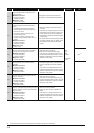
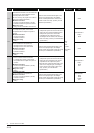
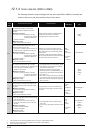
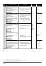
12.1.4 Error code list (2000 to 2999)
The following shows the error messages from the error code 2000 to 2999, the contents and
causes of the errors, and the corrective actions for the errors.
Error
Code
(SD0)
Error Contents and Cause Corrective Action
LED Status
CPU Status
Corresponding
CPU
2000
[UNIT VERIFY ERR.]
In a multiple CPU system, a CPU module
incompatible with the multiple CPU system is
mounted.
■Collateral information
• Common Information:Module No. (Slot No.)
[For Remote I/O network]
Network No./Station No.
• Individual Information:–
■Diagnostic Timing
• When an END instruction executed
Replace the CPU module incompatible with the
multiple CPU system with a CPU module
compatible with the multiple CPU system.
RUN:
Off/On
ERR.:
Flicker/On
CPU Status:
Stop/
Continue
*1
Qn(H)
*3
QnPH
[UNIT VERIFY ERR.]
The I/O module status is different from the I/O
module information at power ON.
• I/O module (or intelligent function module) is not
installed properly or installed on the base unit.
■Collateral information
• Common Information:Module No. (Slot No.)
[For Remote I/O network]
Network No./Station No.
• Individual Information:–
■Diagnostic Timing
• When an END instruction executed
Read the error common information at the GX
Developer, and check and/or change the module
that corresponds to the numerical value (module
number) there.
Alternatively, monitor special registers SD150 to
SD157 using GX Developer, and check and replace
the module where the bit of its data is "1".
Q00J/Q00/Q01
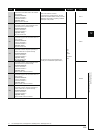
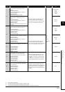
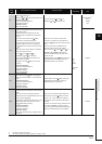
[UNIT VERIFY ERR.]
I/O module information power ON is changed.
• I/O module (or intelligent function module/special
function module) not installed properly or
installed on the base unit.
■Collateral information
• Common Information:Module No. (Slot No.)
[For Remote I/O network]
Network No./Station No.
• Individual Information:–
■Diagnostic Timing
• When an END instruction executed
• Read the common information of the error using
the peripheral device, and check and/or change
the module that corresponds to the numerical
value (module number) there.
• Alternatively, monitor the special registers
SD1400 to SD1431 at a peripheral device, and
change the fuse at the output module whose bit
has a value of "1".
• When a GOT is bus-connected to the main base
unit or extension base unit, check the connection
status of the extension cable and the grounding
status of the GOT.
Qn(H)
QnPH
QnPRH
QnU
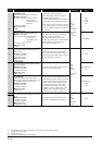
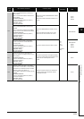
2001
[UNIT VERIFY ERR.]
During operation, a module was mounted on the
slot where the empty setting of the CPU module
was made.
■Collateral information
• Common Information:Module No. (CPU No.)
• Individual Information:–
■Diagnostic Timing
• When an END instruction executed
During operation, do not mount a module on the
slot where the empty setting of the CPU module
was made.
RUN:
Off/On
ERR.:
Flicker/On
CPU Status:
Stop/
Continue
*2
Q00J/Q00/Q01
*3
QnU
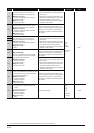
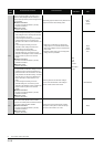
2010
[BASE LAY ERROR]
• More than applicable number of extension base
units have been used.
• When a GOT was bus-connected, the CPU
module was reset while the power of the GOT
was OFF.
■Collateral information
• Common Information:Base No.
• Individual Information:–
■Diagnostic Timing
• At power ON/At reset
• Use the allowable number of extension base
units or less.
• Power on the Progammable Controller and GOT
again.
RUN:
Off
ERR.:
Flicker
CPU Status:
Stop
Q00J/Q00/Q01
*3
QnPRH
Q00UJ
Q00U/Q01U
Q02U
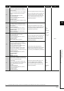
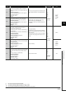
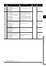
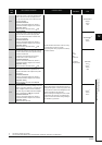
*1 CPU operation can be set in the parameters at error occurrence. (LED indication varies.)
*2 Either error stop or continue can be selected for each module by the parameters.
*3 The function version is B or later.