


Special offers from our partners!

Find Replacement BBQ Parts for 20,308 Models. Repair your BBQ today.
App-150
*1: The module whose first 5 digits of serial No. is "07032" or later.
*2: The module whose first 5 digits of serial No. is "10042" or later.
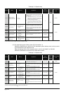
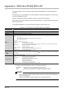
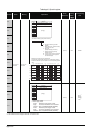
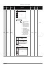
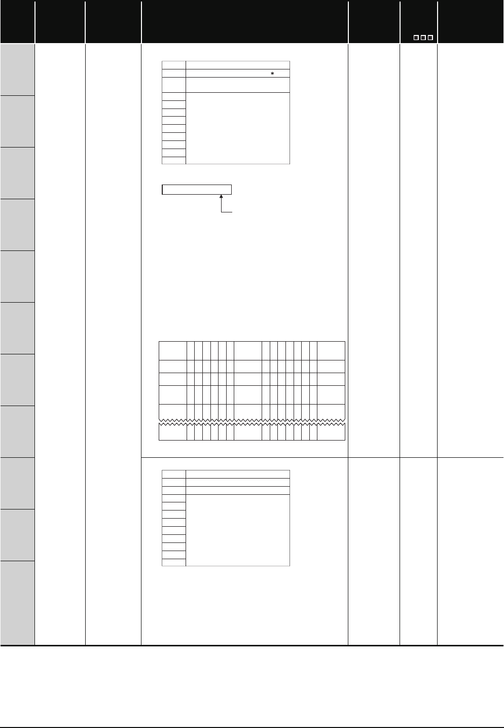
TableApp.4.2 Special register
Number Name Meaning Explanation
Set by
(When Set)
Corres-
ponding
ACPU
D9
Corresponding
CPU
SD5
Error common
information
Error common
information
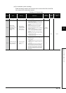
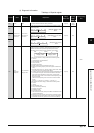
5) Reason(s) for system switching
*13: Details of reason(s) for system switching
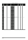
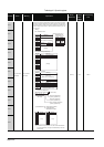
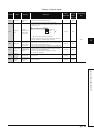
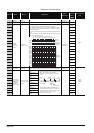
6) Reason(s) for tracking capacity excess error
The block No. when the data amount that can be tracked (100k) is
exceeded is indicated by the bit pattern of the corresponding special
relay.
S (Error) New QnPRH
SD6
SD7
SD8
SD9
SD10
SD11
SD12
SD13
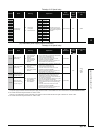
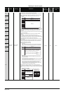
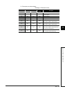
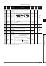
7) Power supply No.
S (Error) New
Qn(H)
*1
QnPH
*1
QnPRH
QnU
*2
SD14
SD15
SD5
SD6
SD7
SD8
SD9
SD10
SD11
SD12
SD13
SD14
SD15
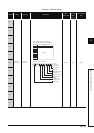
Number Meaning
System switching condition 13
Control system switching
instruction argument
(Empty)
1 : Power-OFF, reset, hardware failure,
watchdog timer error
2 : Stop error
(except watchdog timer error)
3 : System switching request by
network module
16 : Control system switching instruction
17 : Control system switching request
from GX De
veloper
0 : No system switching condition
(default)
SD15
SD5
SD8
SD9
SD6
SD7
0 000000 0 0 0000000
1
(SM1535)
(Block16)
0
b15 b14
0
b13
0
b12
0
b11
0
b10
0
b9
1
(SM1528)
(Block9)
0
b8
1
(SM1520)
(Block1)
b0b7
0
b6
0
b5
0
b4
0
b3
0
b2
0
0 000000 0 0 0000000
0 000000 0 0 0000000
b1
1
(SM1583)
(Block64)
000000 0 0
1
(SM1568)
(Block49)
000000
0 000000 0 0 0000000
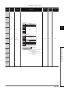
1: Power supply 1 fault
2: Power supply 2 fault
Redundant power supply module
mounted on POWER 1 slot of redundant
base unit (Q38RB, Q68RB, Q65WRB)
"Power
supply
module 1":
Redundant power supply module
mounted on POWER 2 slot of redu
ndant
base unit (Q38RB, Q68RB, Q65WRB)
"Power
supply
module 2":
SD5
SD6
SD7
SD8
SD9
SD10
SD11
SD12
SD13
SD14
SD15
Number Meaning
Base No.
Power supply No.
(Empty)