


Special offers from our partners!

Find Replacement BBQ Parts for 20,308 Models. Repair your BBQ today.
App-160
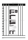
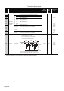
TableApp.4.4 Special register
Number Name Meaning Explanation
Set by
(When Set)
Corres-
ponding
ACPU
D9
Corresponding
CPU
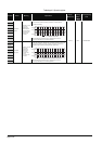
SD202
LED off
command
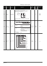
Bit pattern of LED
that is turned off
• Specify the LEDs to be turned off using this register, and turn SM202
from OFF to ON to turn off the specified LEDs.
USER and BOOT can be specified as the LEDs to be turned off.
• Specify the LEDs to be turned off in the following bit pattern.
(Turned off at 1, not be turned off at 0.)
(The Q00UJCPU, Q00UCPU, and Q01UCPU cannot specify the BOOT
LED.)
UNew
Qn(H)
QnPH
QnPRH
QnU
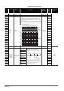
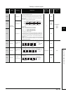
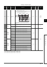
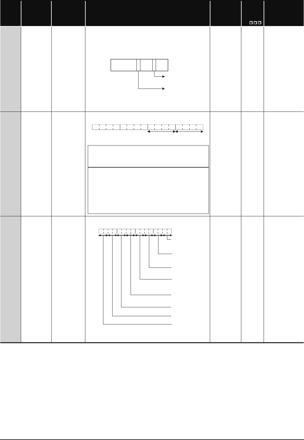
SD203
Operating
status of CPU
Operating status
of CPU
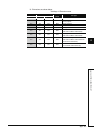
• The CPU operating status is stored as indicated in the following figure:
S (Every END
processing)
D9015
format
change
QCPU
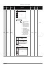
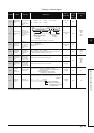
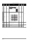
SD204
LED display
color
CPU-LED display
color
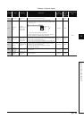
• The LED display color of the LED status shown in SD201 1) to 8).
(The Q00UJCPU, Q00UCPU, and Q01UCPU do not include 5).)
S (status
change)
New QnU
b15 b8 b4 b0
USER
LED
BOOT
LED
Fixed
to 0
Fixed
to 0
Fixed
to 0
b15 b12
b11
b8 b7 b4 b3 b0
1)
to to to to
2)
1): Operating status
of CPU
0:
1:
2:
3:
2): STOP/PAUSE
cause
0:
1:
2:
3:
4: Error
RUN
STEP-RUN (For the QnACPU only)
STOP
PAUSE
Instruction in remote operation program
from RUN/STOP switch ("RUN/STOP/
RESET switch" for Basic model QCPU)
Remote contact
Remote operation from GX Developer/
serial communi
cation, etc.
Internal program instruction
Note: Priority is
earliest first
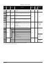
b15 b12 b11 b8 b7 b4 b3 b0
1)RUN LED
0: OFF
1: Green
2)ERROR LED
0: OFF
1: Red
3)USER LED
0: OFF
1: Red
4)BAT. LED
0: OFF
1: Yellow
2: Green
8)MODE LED
0: OFF
1: Green
5)BOOT LED
0: OFF
1: Green
6)Empty
7)Empty