


Special offers from our partners!

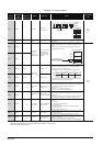
Find Replacement BBQ Parts for 20,308 Models. Repair your BBQ today.
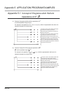
App-194
(16) For redundant systems (Other system CPU information
*1
)
SD1600 to SD1659 is only valid during the back up mode for redundant systems, and
refresh cannot be done when in the separate mode.
SD1651 to SD1699 are valid in either the backup mode or separate mode.
When a stand-alone system SD1600 to SD1699 are all 0.
*2: Shows the special register (SD ) for the host system CPU module.
TableApp.4.20 Special register
Number Name Meaning Explanation
Set by
(When Set)
Corres-
ponding
ACPU
SD *2
Corresponding
CPU
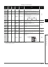
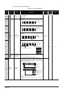
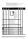
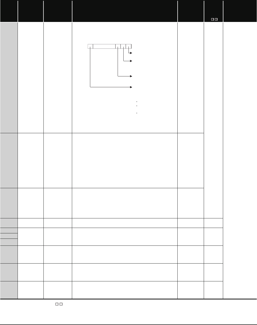
SD1600
System error
information
System error
information
• If an error is detected by the error check for redundant system, the
corresponding bit shown below turns ON. That bit turns OFF when the
error is cleared after that.
• If any of b0, b1, b2 and b15 is ON, the other bits are all OFF.
• In the debug mode, b0, b1, b2 and b15 are all OFF.
S(Every END)
–
QnPRH
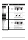
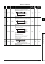
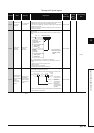
SD1601
System
switching
results
System switching
results
Stores the reasons for system switching.
• Stores the reasons for system switching into SD1601 of both systems
when system switching occarred.
• Initialized to 0 at power OFF to ON/reset to unreset.
• The following shows values stored into this register.
0: Initial value (System switching has not occurred)
1: Power-OFF, Reset, H/W failure, WDT error,(*)
2: CPU stop error (except WDT)
3: System switching request by network module
16: System switching dedicated instruction
17: System switching request from GX Developer
*: When the system is switched by the power OFF/reset of the control
system, "1" is not stored into SD1601 of the new standby system.
S(when system
is switched)
SD1602
System
switching
dedicated
instruction
parameter
System switching
dedicated
instruction
parameter
• Stores the parameters for system switching dedicated instruction
SP.CONTSW.
(The parameters (SD1602) for SP.CONTSW are stored in both systems
A&B)
• SD1602 is only valid when "16" is stored in SD1601.
• This SD1602 is updated once system switch instruction SP.CONTSW is
activated.
S(when system
is switched)
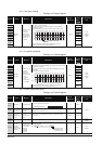
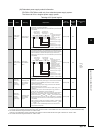
SD1610
Other system
diagnostic error
Diagnostic error
code
• The error value sorted in BIN code.
• Stores SD0 of the other system CPU module
S(Every END) SD0
SD1611 Other system
diagnostic error
occurrence
time
Diagnostic error
occurrence time
• Stores the date and time when diagnostics error occurred corresponding
to error code stored in SD1610.
• Data format is the same as SD1 to SD3.
• Also, stores the value to SD1 to SD3.
S(Every END)
SD1 to
SD3
SD1612
SD1613
SD1614
Other system
error
information
category
Error information
category code
• Stores the category code corresponding to the error comment
information/individual information code.
• Data format is the same as SD4.
• Also, stores the value to SD4.
S(Every END) SD4
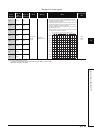
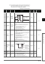
SD1615
to
SD1625
Other system
error common
information
Error common
information
• Stores the common information corresponding to the error code stored
in this system CPU.
• Data composition is the same as SD5 to SD15.
• Also, stores the value to SD5 to SD15.
S(Every END)
SD5 to
SD15
SD1626
to
SD1636
Other system
error individual
information
Error individual
information
• Stores the individual information corresponding to the error code stored
in this system CPU.
• Data composition is the same as SD16 to SD26.
• Also, stores the value to SD16 to SD26.
S(Every END)
SD16 to
SD26
b1 b0b15 b2
Fixed to 0
Tracking cable is not
connected or damaged
Each bit
0: OFF
1: ON
Power-OFF, reset,
watchdog timer error or
hardware failure occurred
in other system
Bit turns on when failing to
connect with other system.
The following
causes are
shown below:
Tracking H/W failure
Host system WDT
error
Cannot recognize
other system therefore
causing error
SD1600
Other system stop error
(except watchdog timer
error)