


Special offers from our partners!

Find Replacement BBQ Parts for 20,308 Models. Repair your BBQ today.
2-28
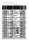
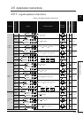
2.4.8 Other convenient instructions
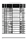
Table 2.17 Other convenient instructions
Category
Instruction Symbol
Symbol Processing Details
Execution
Condition
Number of Basic Steps
Subset
See for Description
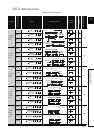
Up/Down
counter
UDCNT1
4 - 6-143
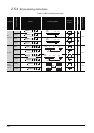
UDCNT2
4 - 6-146
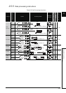
Teaching
timer
TTMR
3 - 6-149
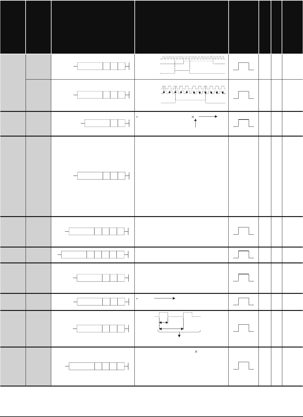
Special
timer
STMR
• The 4 points from the bit device
designated by (D) operate as shown
below, depending on the ON/OFF
status of the input conditions for the
STMR instruction:
(D)+0: Off delay timer output
(D)+1: One shot after off timer output
(D)+2: One shot after on timer output
(D)+3
:
On delay and off delay timer
output
3 - 6-151
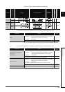
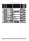
Shortest
direction
control
ROTC
• Rotates a rotary table with n1 divisions
from the stop position to the position
designated by (S+1) in the shortest
direction.
5 - 6-154
Ramp
signal
RAMP
• Changes device data designated by D1
from n1 to n2 in n3 scans.
6 - 6-157
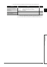
Pulse
density
SPD
• Counts the pulse input from the device
designated by (S) for the duration of
time designated by n, and stores the
count in the device designated by (D).
4 - 6-160
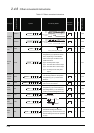
Pulse
output
PLSY
4 - 6-162
Pulse
width
modulation
PWM
4 - 6-164
Matrix
input
MTR
• Reads data of 16 points n rows from
the devices starting from the one
specified by (S), and stores them to the
devices starting from the one specified
by (D2).
5 - 6-166
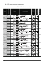
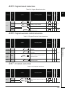
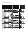
UDCNT1 nSD
(S)+1
Up
Down
Up
(S)+0
Present Cn value
Cn contact
1234 6765 3210-1-2 -3-2 -1 00 45
UDCNT2 nSD
(S)+0
(S)+1
Present Cn value
Cn contact
12 45 43 1 0-10 3 2
TTMR nD
(Time that TTMR is ON)
n
(D)
n=0:1, n=1:10n, n=2:100
STMR nSD
ROTC n2n1SD
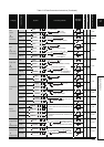
RAMP D1 n3n1 n2 D2
SPD nSD
PLSY n1 n2 D
(n1)Hz (D)
Output n2 times
PWM n1 n2 D
n1
n2
(D)
MTR D2 nD1S