


Special offers from our partners!

Find Replacement BBQ Parts for 20,308 Models. Repair your BBQ today.
6-165
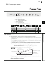
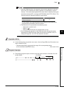
PWM
1
2
3
4
4
6
7
8
6.8 Other Convenient Instructions
6.8.9 Pulse width modulation (PWM)
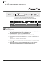
1. With the PWM instruction, the argument device data is registered in the work
area of the CPU module and counting operation is processed as a system
interrupt. (The device data registered in the work area is cleared by turning the
execution command OFF, or turning the STOP/RUN switch STOP RUN.) The
interrupt interval of individual modules is shown below:
For this reason, the PWM instruction can be used only once within all the
programs being executed by the CPU module.
2. The instruction is not processed in the following cases:
• When both n1 and n2 are 0
• When n1 n2
• When the PWM instruction is executed twice or more.
3. Do not change the argument for the PWM instruction during pulse output
directed by the PWM instruction (while the execution command is ON). To
change the argument, turn OFF the execution command.
Operation Error
(1) In the following case, an operation error occurs, the error flag (SM0) turns ON, and an error
code is stored into SD0.
• The device specified by exceeds the range of the corresponding device.
(For the Universal model QCPU only.) (Error code: 4101)
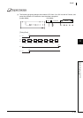
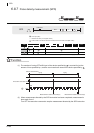
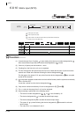
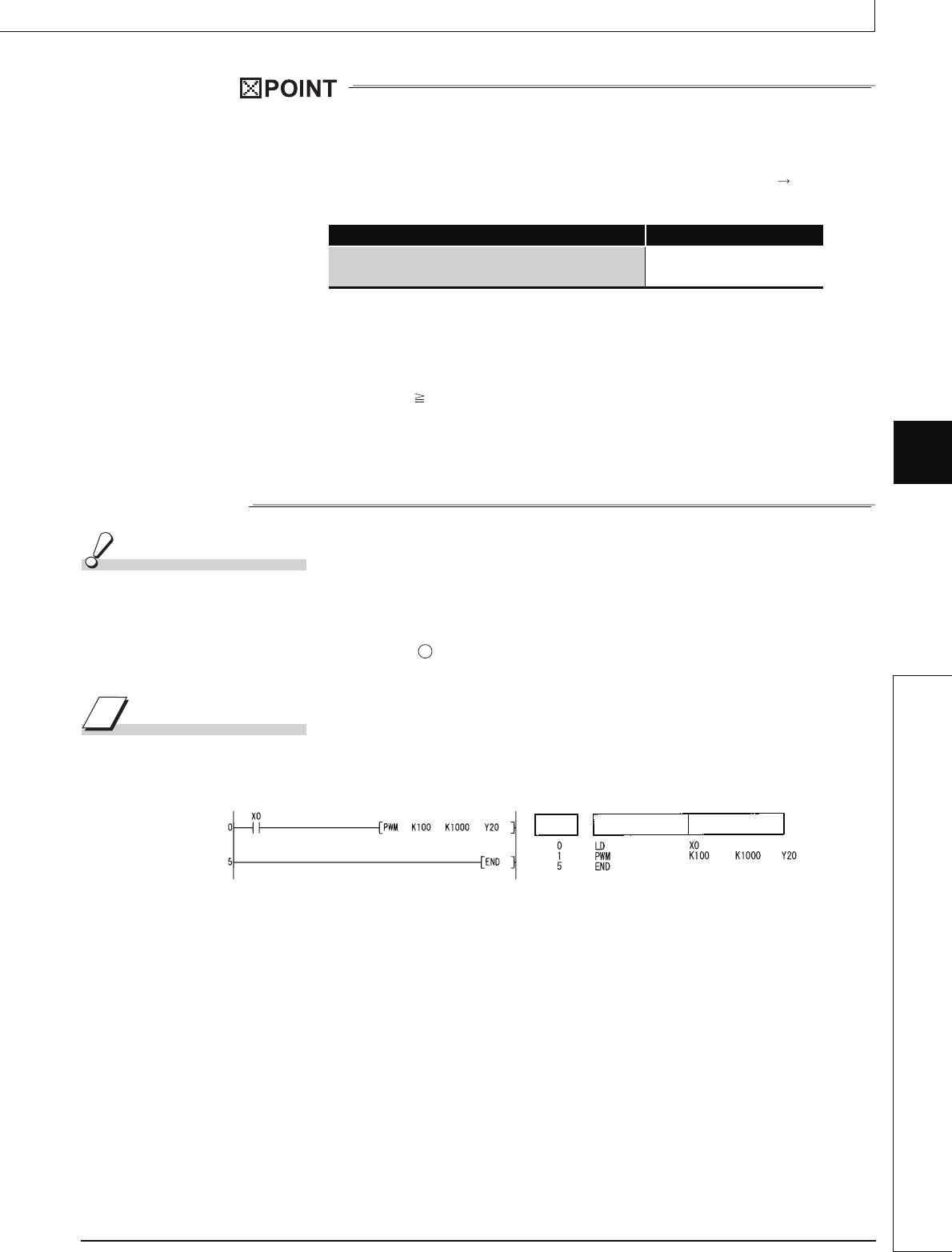
Program Example
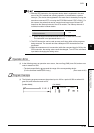
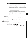
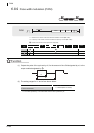
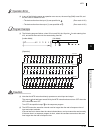
(1) The following program outputs a 100 ms pulse once each second to Y20 when X0 is ON.
[Ladder Mode] [List Mode]
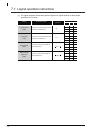
CPU Module Type Name Interrupt Interval of n1, n2
High Performance model QCPU, Process CPU,
Universal model QCPU
1 ms
D
Step
Instruction
Device