


Special offers from our partners!

Find Replacement BBQ Parts for 20,308 Models. Repair your BBQ today.
10-16
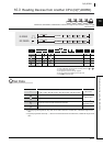
D(P).DDWR
In any of the following cases, the instruction is completed abnormally, and an error code is
stored into a device specified at completion status storage device ( +0).
(1) The request of the instruction to the target CPU is more than the acceptable value (no empty
blocks exist in the multiple CPU high speed transmission area).
(Error code: 0010
H)
(2) A device for another CPU specified at cannot be used at another CPU, or is out of device
range. (Error code: 1001H)
(3) The number of write points set with the D(P).DDWR instruction is 0.
(Error code: 1080
H)
(4) The response of the instruction from another CPU cannot be returned (no empty blocks exist
in the multiple CPU high speed transmission area). (Error code: 1003
H)
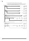
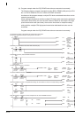
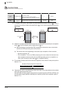
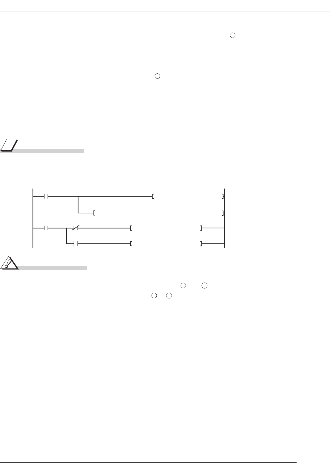
Program Example
(1) This program stores data by 10 words starting from DO in host CPU into W10 or later in CPU
No.2 when XO turns on.
[Ladder mode]
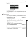
Caution
(1) Digit specification of bit device is possible for n, , and . Note that when the digit
specification of bit device is made to or , the following conditions must be met.
• Digits are specified by 16 bits (4 digits).
• The start bit device is multiples of 16 (10
H).
(2) Execute this instruction after checking that the write target CPU is powered on. Not doing so
may end up no processing.
(3) If changing a range of the device specified at setting data between after execution of the
instruction and turn-on of the completion device, data to be stored by system (completion
status, completion device) cannot be stored normally.
(4) SB, SW, SM, and SD include system information area. Take care not to destroy the system
information when writing data to the devices above with the D(P).DDWR instruction of the
multiple CPU high-speed transmission dedicated instruction.
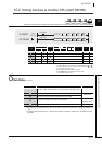
S1
S1
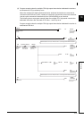
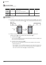
X0
Execution command
of the instruction
MOVP K10 D101
DP.DDWR H3E1 D100 D0 W10 M100
M100
Completion device
M101
M101
Normal completion Program
Error completion Program
The number of write points "10" is
stored into D101, setting device of
the number of write points (S1+1)
of control data.
D0 to D9 in host CPU are stored into
W10 to W19 in CPU No.2.
S2
D1
S2
D1