


Special offers from our partners!

Find Replacement BBQ Parts for 20,308 Models. Repair your BBQ today.
7-165
TO(P),DTO(P)
1
2
3
4
6
6
7
8
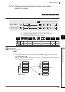
7.8 Buffer memory access instruction
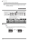
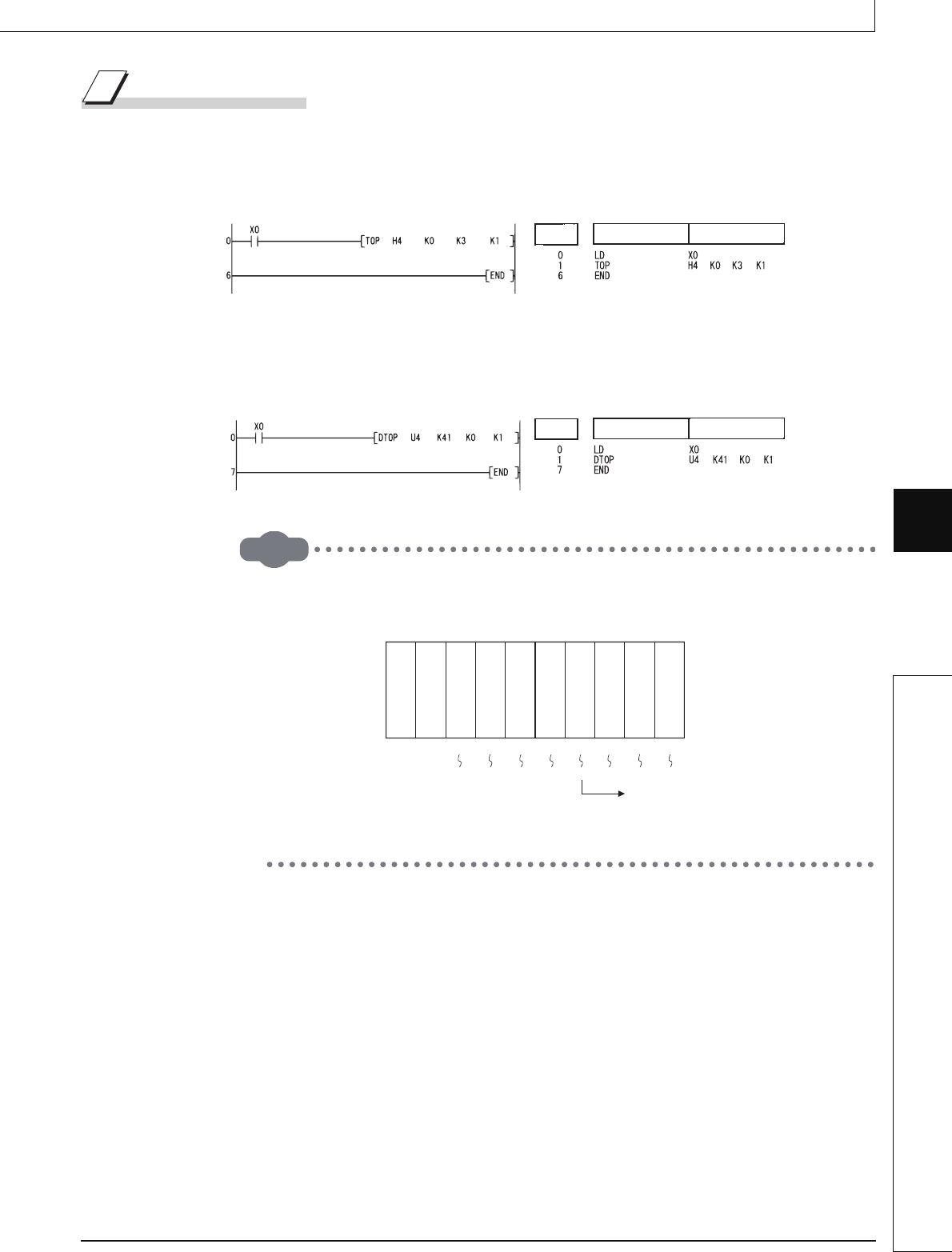
7.8.2 Writing 1-/2-word data to intelligent function module (TO(P),DTO(P))
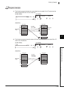
Program Example
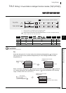
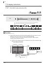
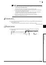
(1) The following program sets the CH1 and CH2 of the Q68ADV mounted at the I/O numbers
040 to 04F to the "A/D conversion" mode, when X0 is turned ON.
(Writes 3 into the buffer memory address 0.)
[Ladder Mode] [List Mode]
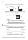
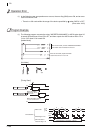
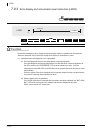
(2) The following program sets the X-axis current value of the AD71 mounted at I/O numbers
040 to 05F to 0 when X0 is turned ON. (Writes 0 to addresses 41, 42 of the buffer memory.)
[Ladder Mode] [List Mode]
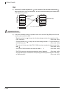
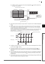
Remark
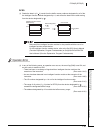
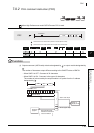
1. The value of n1 is specified by the upper 3 digits of hexadecimal 4-digit
representation of the head I/O number of the slot in which an intelligent
function module is mounted.
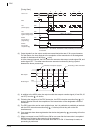
2. QCPU establishes the automatic interlock of the TO/DTO instructions.
Step
Instruction
Device
Step
Instruction
Device
Q
X
10
Q
X
10
Q
X
10
Q
X
10
Q
68
A
D
V
Q
Y
41
P
Q
Y
10
Q
Y
10
X0000
X000
F
X0010
X001F
X0020
X002F
X0030
X003F
0040
004F
Y0050
Y006F
Y0070 Y0080
Y008FY007F
Power supply module
CPU module
Head I/O number
of the reading
K4 or H4