


Special offers from our partners!

Find Replacement BBQ Parts for 20,308 Models. Repair your BBQ today.
App-193
8
8
8
8
A
8
7
8
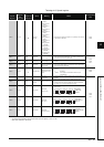
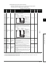
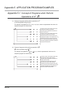
Appendix 4 SPECIAL REGISTER LIST
(15) For redundant systems (Host system CPU information
*1
)
SD1510 to SD1599 are only valid for redundant systems.
They are all set to 0 for stand-alone systems.
*1: The information of the host CPU module is stored.
TableApp.4.19 Special register
Number Name Meaning Explanation
Set by
(When Set)
Corres-
ponding
ACPU
D9
Corresponding
CPU
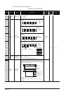
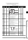
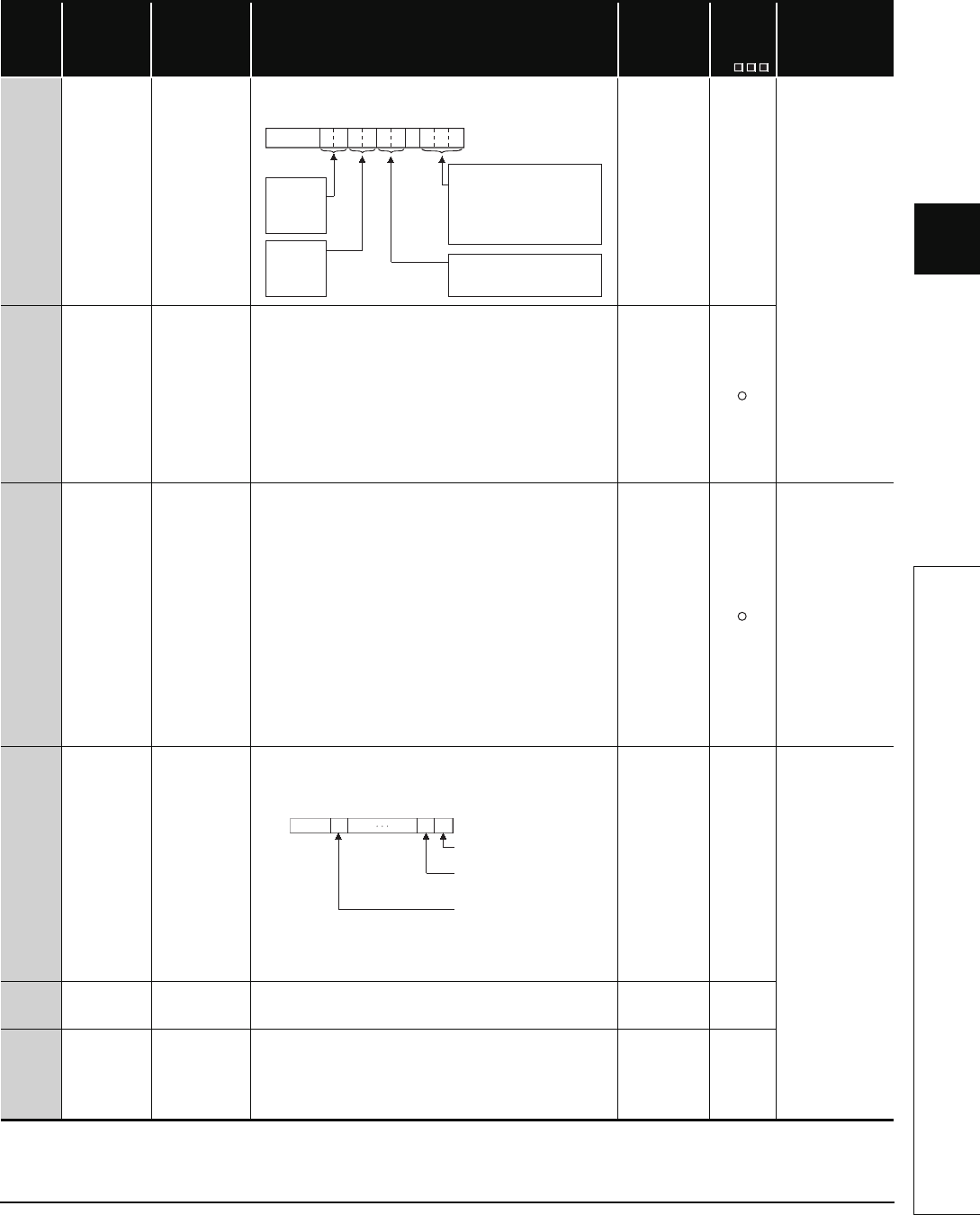
SD1585
Redundant
system LED
status
4 LED states
• BACKUP
• CONTROL
• SYSTEM A
• SYSTEM B
The LED status for BACKUP, CONTROL, SYSTEM A, SYSTEM B is
stored in the following format:
S (status
change)
New
QnPRH
SD1588
Reason(s) for
system switch-
ing
Reason(s) for
system switching
that occurred in
host station
Stores the reason(s) for system switching on the host system.
The following values are stored corresponding to the methods for system
switching:
Initialized to 0 when the power supply is switched off and then on or the
RESET switch is set to the RESET position and then to the neutral
position.
0: Initial value (control system has not been switched)
1: Power off, Reset, H/W failure, WDT error,
2: CPU stop error (except WDT)
3: System switching request from network module
16: System switching dedicated instruction
17: System switching request from GX Developer
S (when
condition occurs)
SD1589
Reason(s) for
system
switching failure
conditions
Reason(s) for
system switching
failure No.
• Stores the reason(s) for system switching failure.
0: System switching normal (default)
1: Tracking cable is not connected , tracking cable error, FPGA circuit
failure.
2: H/W failure, power-OFF, Reset, WDT error on the standby system
3: H/W failure, power-OFF, Reset, WDT error on the Control system
4: Tracking data transfer initialization
5: Communication timeout
6: Serious error(except WDT error) on the Standby system
7: There is difference between both systems
(detected as Backup mode only)
8: During memory copy from control system to standby system
9: During online program change
10: During detection of intelligent function module failure on the standby
system
11: System switching being executed
• Resets to "0" when host system is powered on.
• Resets to "0" once system has been switched successfully.
S(when system
is switched)
QnPRH
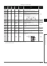
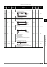
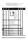
SD1590
Network module
head address,
which requested
system
switching
Network module
head address,
which requested
system switching
• Stores head address of network module which a system switch request
was initiated.
• Turns off automatically by system, after network error is reset by user.
• Please refer to SD1690 which stores the corresponding head address of
network module on other system.
S (Error/Status
change)
New
QnPRH
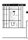
SD1595
Memory copy
target I/O
number
Memory copy
target I/O number
• Stores the memory copy target I/O No.(Standby system CPU module:
3D1H) of before SM1595 is turned from OFF to ON.
UNew
SD1596
Memory copy
status
Memory copy
status
• Stores the execution result of Memory copy function.
0 : Memory copy successfully completed
4241H : Standby system power supply off
4242
H : Tracking cable is disconnected or is damaged
4247
H : Memory copy function is being executed
4248H : Unsupported memory copy destination I/O Number
S (Status
change)
New
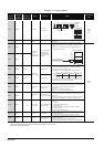
b0tob2b3b4b5b6b7b8b10b9b15
00
to
SYSTEM B
0: Off
1: On
2: Flicker
SYSTEM A
0: Off
1: On
2: Flicker
CONTROL
0: Off
1: On
BACKUP
0: Off
1: On (red)
2:
3: On(green)
4: Flicker(green)
Flicker(red)
5: On (orange-yellow)
6: Flicker
(orange-yellow)
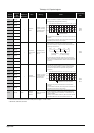
b1 b0b15 b11to to
0
0/1
0/10
Module 0:
Module 1:
Module11:
SD1590
Each bit
0:OFF
1:ON
to
CPU module is invalid
as it is 2-slot model.
Module on the right
side of the CPU module
Module at the
rightmost end of the
12-slot base (Q312B)