


Special offers from our partners!

Find Replacement BBQ Parts for 20,308 Models. Repair your BBQ today.
5-6
LDP,LDF,ANDP,ANDF,ORP,ORF
(2) LDF is the trailing edge pulse operation start instruction, and is ON only at the trailing edge
of the designated bit device (when it goes from ON to OFF).
If a word device has been designated, it is ON only when the designated bit changes from 1
to 0.
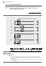
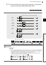
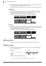
ANDP, ANDF
(1) ANDP is a leading edge pulse series connection instruction, and ANDF is a trailing edge
pulse series connection instruction. They perform an AND operation with the operation
result to that point, and take the resulting value as the operation result.
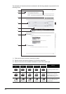
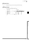
The ON/OFF data used by ANDP and ANDF are indicated in the table below:
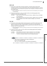
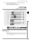
ORP, ORF
(2) ORP is a leading edge pulse parallel connection instruction, and ORF is a trailing edge pulse
serial connection instruction. They perform an OR operation with the operation result to that
point, and take the resulting value as the operation result.
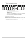
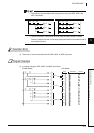
The ON/OFF data used by ORP and ORF are indicated in the table below:
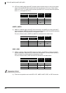
Operation Error
(1) There are no operation errors with LDP, LDF, ANDP, ANDF, ORP, or ORF instruction.
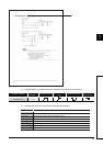
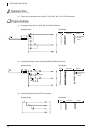
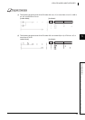
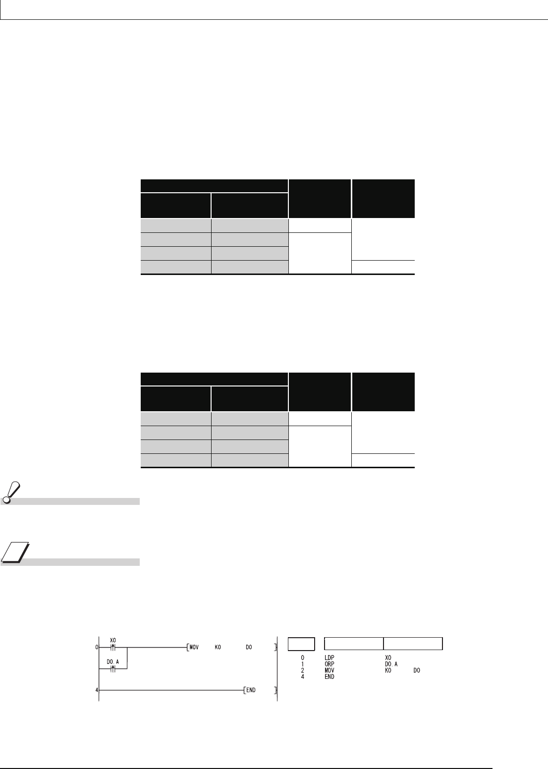
Program Example
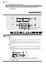
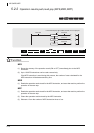
(1) The following program executes the MOV instruction at input X0, or at the leading edge of
b10 (bit 11) of data register D0.
[Ladder Mode] [List Mode]
*1: Word device bit designation is performed in hexadecimal. Bit b10 of D0 will be D0.A.
Device Specified in ANDP or ANDF
ANDP State ANDF State
Bit Device
Bit Designated for
Word Device
OFF to ON 0 to 1 ON
OFF
OFF 0
OFF
ON 1
ON to OFF 1 to 0 ON
Device Specified in ORP or ORF
ORP State ORF State
Bit Device
Bit Designated for
Word Device
OFF to ON 0 to 1 ON
OFF
OFF 0
OFF
ON 1
ON to OFF 1 to 0 ON
*1
Step
Instruction
Device