


Special offers from our partners!

Find Replacement BBQ Parts for 20,308 Models. Repair your BBQ today.
7-397
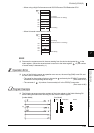
KEY
1
2
3
4
6
6
7
8
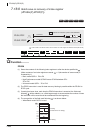
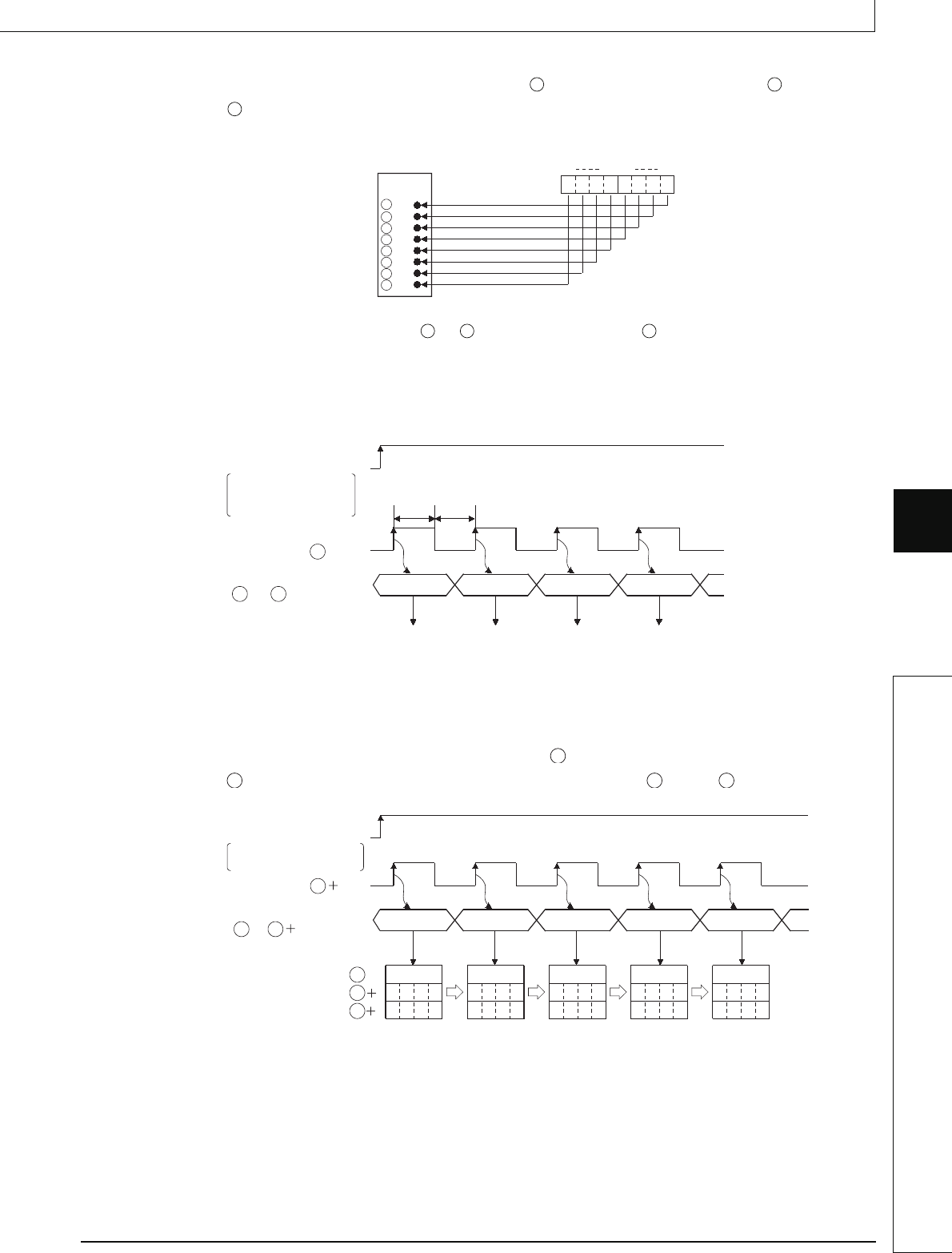
7.18 Other instructions
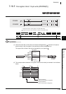
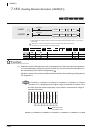
7.18.7 Numerical key input from keyboard (KEY)
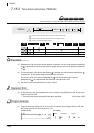
(2) Numerical input to input (X) designated by undergoes bit development at through
+7 and is input as the ASCII code corresponding to the numbers.
ASCII code which can be input is from 30
H (0) to 39H (9), and from 41H (A) to 46H (F).
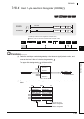
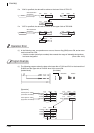
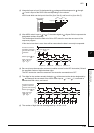
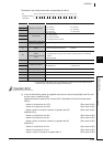
(3) After ASCII code is input to to +7, the strobe signal at +8 goes ON to incorporate the
designated numbers internally.
The strobe signal should be held at its ON or OFF status for more than one scan of the
sequence program.
If this time is less than 1 scan, there will be cases when the data is correctly incorporated.
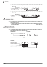
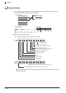
(4) Be sure to keep the execution command (condition contact for the KEY instruction) ON until
the specified number of digits has been input.
The KEY instruction cannot be executed if the execution command turns OFF.
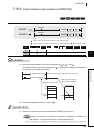
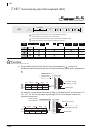
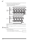
(5) The digits for the numbers actually fetched to will be stored at the device designated by
, and these will be converted to the ASCII codes input at +1 and +2, converted to
hexadecimal BIN values, and stored.
(6) The number of digits that can be designated by n is from 1 to 8.
S S
S
Input module
"1"(31
H
)=
0
b7 b4 b0b3
0
11
000
1
(3
H
)(1
H
)
S
S
S
S
S
S
S
S
+1
+2
+3
+4
+5
+6
+7
S S S
31
H
32
H
33
H
34
H
Execution command
Condition contact for
the execution of KEY
instruction
Strobe signal ( +8)
ASCII code input
(
to
+7)
S
SS
ON for 1 scan
or longer
OFF for 1 scan
or longer
Fetches "1" Fetches "2"
Fetches "3"
Fetches "4"
D1
D1 D1 D1
31
H
33
H
35
H
37
H
39
H
0013
0000
2
013
5
0000
3
13
5
7
0000
4
3
5
79
000
1
5
0001
0000
1
Execution command
Condition contact for the
execution of KEY instruction
Strobe signal (8)
ASCII code input
(
to 7)
S
D1
S S
D1
D1
1
2