


Special offers from our partners!

Find Replacement BBQ Parts for 20,308 Models. Repair your BBQ today.
App-188
*1: The relevant modules are as follows:
• The Universal model QCPU whose serial number (first five digits) is "10102" or later.
• Q00UJCPU, Q00UCPU, Q01UCPU
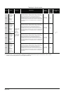
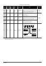
TableApp.4.13 Special register
ACPU
Special
Register
Special
Register
after
Conversion
Special
Register for
Modification
Name Meaning Details
Corresponding
CPU
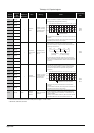
D9100 SD1100
–
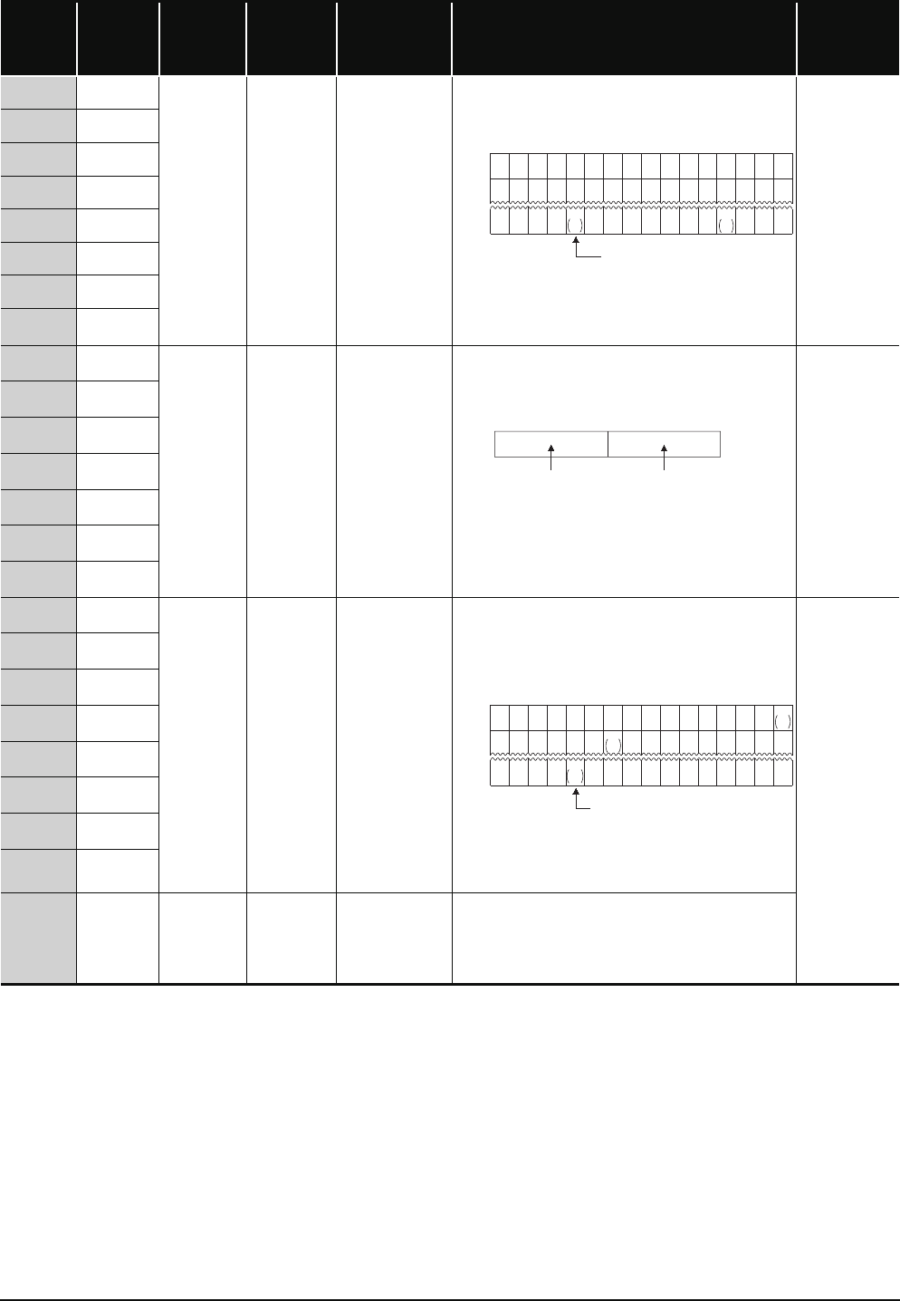
Fuse blown
module
Bit pattern in units of
16 points, indicating
the modules whose
fuses have blown
• Output module numbers (in units of 16 points), of which fuses have
blown, are entered in bit pattern. (Preset output module numbers
when parameter setting has been performed.)
• Fuse blow check is executed also to the output module of remote I/
O station.
(If normal status is restored, clear is not performed. Therefore, it is
required to perform clear by user program.)
Qn(H)
QnPH
QnU
*1
D9101 SD1101
D9102 SD1102
D9103 SD1103
D9104 SD1104
D9105 SD1105
D9106 SD1106
D9107 SD1107
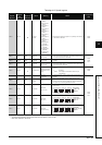
D9108 SD1108
–
Step transfer
monitoring timer
setting
Timer setting valve
and the F number at
time out
• Set the value of the step transition monitoring timer and the
annunciator number (F number) that will be turned ON when the
monitoring timer times out.
• By turning ON any of SM1108 to SM1114, the monitoring timer
starts. If the transition condition following a step which corresponds
to the timer is not established within set time, set annunciator (F) is
turned on.)
Qn(H)
QnPH
D9109 SD1109
D9110 SD1110
D9111 SD1111
D9112 SD1112
D9113 SD1113
D9114 SD1114
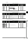
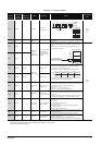
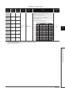
D9116 SD1116
–
I/O module
verification error
Bit pattern, in units of
16 points, indicating
the modules with
verification errors.
• When I/O modules, of which data are different from those entered
at power-ON, have been detected, the I/O module numbers (in
units of 16 points) are entered in bit pattern. (Preset I/O module
numbers set in parmeters when parameter setting has been
performed.)
• I/O module verify check is executed also to remote I/O station
modules.
(If normal status is restored, clear is not performed. Therefore, it is
required to perform clear by user program.)
Qn(H)
QnPH
QnU
*1
D9117 SD1117
D9118 SD1118
D9119 SD1119
D9120 SD1120
D9121 SD1121
D9122 SD1122
D9123 SD1123
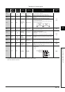
D9124 SD1124 SD63
Number of
annuciator
detections
Number of annuciator
detections
• When one of F0 to 255 (F0 to 2047 for AuA and AnU) is turned on
by SET F instruction 1 is added to the contents of SD63. When
RST F or LEDR instruction is executed, 1 is subtracted from the
contents of SD63.
• Quantity, which has been turned on by SET F instruction is stored
into SD63 in BIN code. The value of SD63 is maximum 16.
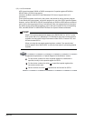
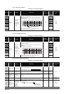
b15 b14b13b12b11b10
b9
b8
b7 b6 b5 b4 b3 b2 b1 b0
00000000
1
(Y80)
000
1
(YC0)
000
0000000000000000
00000000000000
1
Y7
B0
1
Y7
30
SD1100
SD1101
SD1107
Indicates fuse blow.
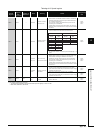
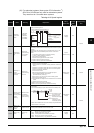
b15 b7 b0b8to to
(02 to 255)
F number setting Timer time limit setting
(1 to 255 s:(1 s units))
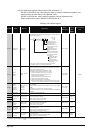
b15b14b13b12b11b10 b9 b8 b7 b6 b5 b4 b3 b2 b1 b0
0000000000000
000000000000000
00000000000000
1
XY
7B0
SD1116
SD1117
SD1123
1
XY
0
1
XY
190
0
00
Indicates an I/O module verify error.