


Special offers from our partners!

Find Replacement BBQ Parts for 20,308 Models. Repair your BBQ today.
App-148
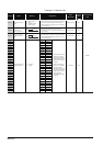
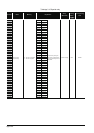
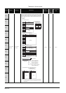
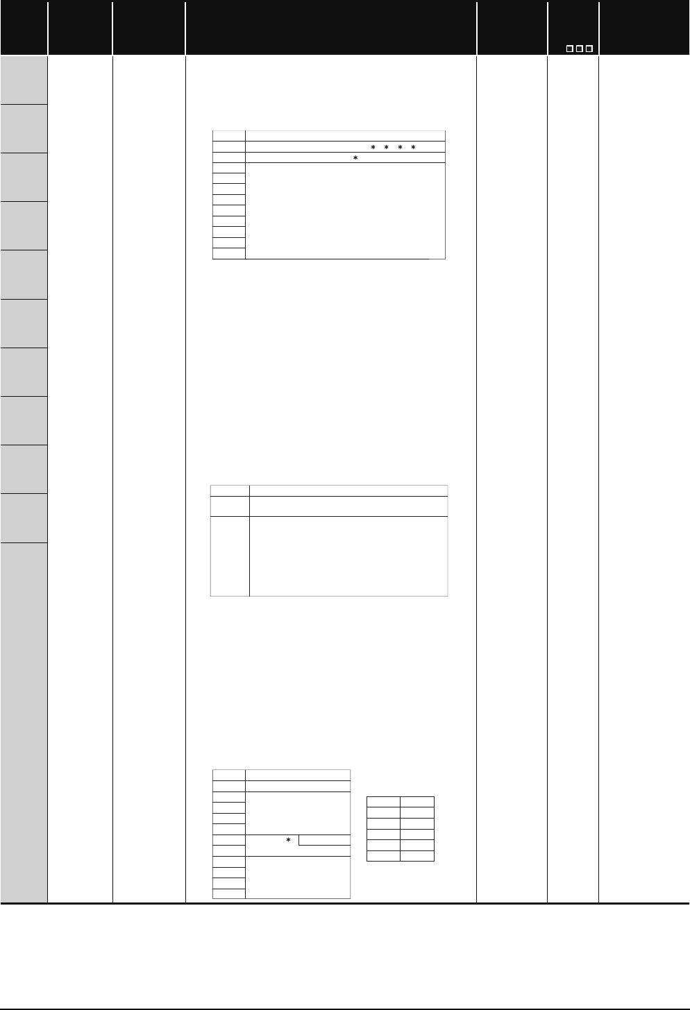
TableApp.4.2 Special register
Number Name Meaning Explanation
Set by
(When Set)
Corres-
ponding
ACPU
D9
Corresponding
CPU
SD5
Error common
information
Error common
information
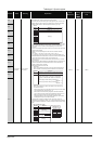
• Common information corresponding to the error codes (SD0) is stored
here.
• The following ten types of information are stored here:
• The error common information type can be judged by the "common infor-
mation category code" in SD4. (The values of the "common information
category code" stored in SD4 correspond to following 1) to 8).)
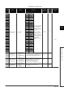
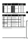
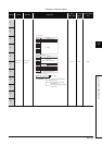
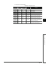
1) Slot No.
*1: For a multiple CPU system that consists of the Basic model QCPU, High
Performance model QCPU, Process CPU, Universal model QCPU, the
slot number or CPU number is stored depending on the error that
occurred.
Slot 0 in the multiple CPU system is the one on the slot on the right of the
rightmost CPU module.
(Refer to the corresponding error code for which number has been
stored.)
No. 1 CPU: 1, No. 2 CPU: 2, No. 3 CPU: 3, No. 4 CPU: 4
*2: If a fuse blown or I/O verify error occurred in the module loaded in the
MELSECNET/H remote I/O station, the network number is stored into the
upper 8 bits and the station number into the lower 8 bits.
Use the I/O No. to check the module where the fuse blown or I/O verify
error occurred.
*3: 255 is stored into SD5 of the Basic model QCPU when an instruction, etc.
has been executed for the module later than the one on the last slot
where a module can be mounted.
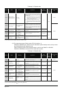
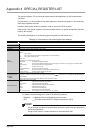
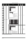
*4: Definitions of base No. and slot No.
<Base No.>
Value used to identify the base unit on which the CPU module has
been mounted. The following shows the definition of the base No.
<Slot No.>
Value used to identify the slot of each base unit and the module
mounted on that slot.
•The I/O slot 0 (slot on the right side of the CPU slot) of the main base
unit is defined as the slot of "Slot No. = 0".
•The slot Nos. are consecutively assigned to the slots of the base
units in order of the main base unit and extension base units 1 to 7.
•When the number of base unit slots has been set in the I/O
assignment setting of the PLC parameter dialog box, the slot Nos.
are assigned for only the number of set slots.
*5: When 0FFFFH is stored into SD6 (I/O No.), the I/O No. cannot be
identified due to overlapping I/O No., etc. in the I/O assignment setting of
the PLC parameter dialog box. Therefore, identify the error location using
SD5.
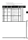
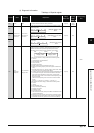
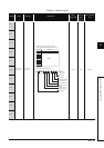
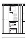
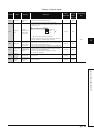
2) File name/Drive name
S (Error) New QCPU
SD6
SD7
SD8
SD9
SD10
SD11
SD12
SD13
SD14
SD15
1, 2, 3, 4
SD5
SD6
SD7
SD8
SD9
SD10
SD11
SD12
SD13
SD14
SD15
Number
Slot No./CPU No./Base No.
I/O No. 5
Meaning
(Empty)
0
1 to 7
Base No.
Indicates the main base unit mounted with the CPU
module.
Indicates the extension base unit. The stage
number setting made by the stage number setting
connector on the extension base u
nit is the base
No.
When stage number setting is extension 1:
Base No. = 1
when stage number setting is extension 7:
Base No. = 7
Definition
SD5
SD6
SD7
SD8
SD9
SD10
SD11
SD12
SD13
SD14
SD15
2E
H(.)
6
ABCDEFGH. IJK
42H(B) 41H(A)
44
H(D) 43H(C)
46
H(F) 45H(E)
48
H(H) 47H(G)
49
H(I) 2EH(.)
4B
H(K) 4AH(J)
b15 to b8 b7 to b0
Number Meaning
Drive
File name
(ASCII code: 8 characters)
Extension
(ASCII code: 3 characters)
(Empty)
(Example) File name =