


Special offers from our partners!

Find Replacement BBQ Parts for 20,308 Models. Repair your BBQ today.
App-117
8
8
8
8
A
6
7
8
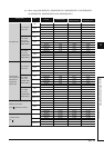
Appendix2 CPU PERFORMANCE COMPARISON
Appendix 2.1 Comparison of Q with AnNCPU, AnACPU, and AnUCPU
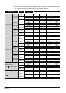
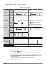
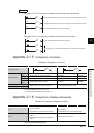
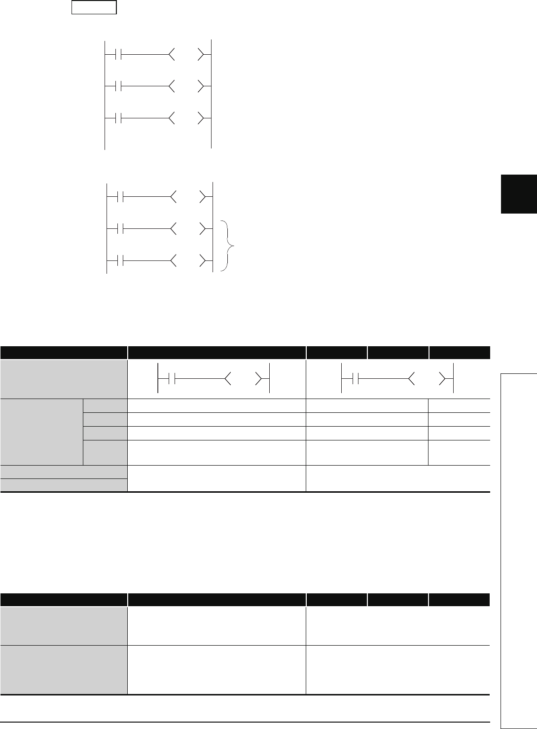
• For timers T0 to T2, the program is created in the order the timer operates later.
• For timers T0 to T2, the program is created in the order of timer operation.
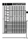
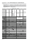
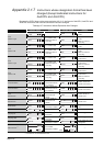
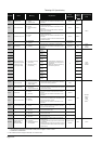
Appendix 2.1.5 Comparison of counters
TableApp.2.5 Comparison of Counters
*1: The Q00J/Q00/Q01CPU can use Z0 to Z9.
The Universal model QCPU can use Z0 to Z19.
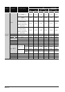
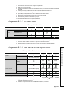
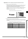
Appendix 2.1.6 Comparison of display instructions
TableApp.2.6 Comparison of Display Instructions
*1: Unusable for the Q00J/Q00/Q01CPU.
Function QCPU AnUCPU AnACPU AnNCPU
Designation method
Index modification
Contact
• Enabled (only Z0 and Z1 are usable) • Enabled • Disabled
Coil
• Enabled (only Z0 and Z1 are usable) • Disabled • Disabled
Set value
• Disabled • Disabled • Disabled
Present
value
• Enabled (Z0 to Z15 are usable)
*1
• Enabled • Enabled
Update processing for present value
• When OUT Cn instruction is executed • When END processing is done
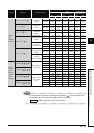
Contact ON/OFF processing
Instruction QCPU AnUCPU AnACPU AnNCPU
PR
*1
• When SM701 is OFF: Output continued until
00
H
encountered
• When SM701 is ON: 16 characters output
• When M9049 is OFF: Output continued until 00
H
encountered
• When M9049 is ON: 16 characters output
PRC
*1
• When SM701 is OFF: 32-character comment
output
• When SM701 is ON: Upper 16 characters
output
16-character comment output
Example
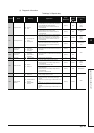
T2 timer starts measurement from the next scan after turning the contact of T1 ON.
T2
K1
T1
T1
K1
T0
T0
K1
X0
T1 timer starts measurement from the next scan after turning the contact of T0 ON.
T0 timer starts measurement when X0 is turned ON.
T0
K1
X0
T1
K1
T0
T2
K1
T1
T0 timer starts measurement when X0 is turned ON.
Contacts of T1 and T2 timers are turned ON when contact of T0 is turned ON.
C0
K100
C0
K100