


Special offers from our partners!

Find Replacement BBQ Parts for 20,308 Models. Repair your BBQ today.

App-197
8
8
8
8
A
8
7
8
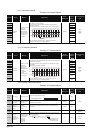
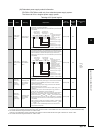
Appendix 4 SPECIAL REGISTER LIST
(18) Redundant power supply module information
SD1780 to SD1789 are valid only for a redundant power supply system.
The bits are all 0 for a singular power supply system.
*1: The "power supply 1" in dicates the redundant power supply module mounted on the POWER 1 slot of the redundant base unit (Q38RB/68RB/Q65WRB).
The "power supply 2" indicates the redundant power supply module mounted on the POWER 2 slot of the redundant base unit (Q38RB/68RB/Q65WRB).
*2: The module whose first 5 digits of serial No. is "07032" or later.
However, for the multiple CPU system configuration, this applies to all CPU modules whose first 5 digits of serial No. are "07032" or later.
*3: The module whose first 5 digits of serial No. is "10042" or later.
TableApp.4.22 Special register
Number Name Meaning Explanation
Set by
(When Set)
Corres-
ponding
ACPU
D9
Corresponding
CPU
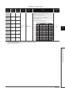
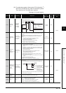
SD1780
Power supply
off detection
status
Power supply off
detection status
• Stores the status of the redundant power supply module with input
power OFF in the following bit pattern.
• Stores 0 when the main base unit is not the redundant power main base
unit (Q38RB).
• When configuring multiple CPU, the status is stored to 1st CPU module.
S(Every END) New
Qn(H)
*2
QnPH
*2
QnPRH
QnU
*3
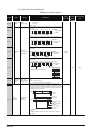
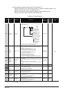
SD1781
Power supply
failure detection
status
Power supply
failure detection
status
• Stores the failure detection status of the redundant power supply module
in the following bit pattern. (The corresponding bit is cleared to 0 when
the input power to the faulty redundant power supply module is switched
OFF after detection of the redundant power supply module failure.)
• Stores 0 when the main base unit is not the redundant power main base
unit (Q38RB).
• When configuring multiple CPU, the status is stored to 1st CPU module.
S(Every END) New
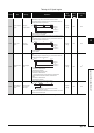
SD1782
Momentary
power failure
detection
counter for
power supply
1
*1
Momentary power
failure detection
count for power
supply 1
• Counts the number of times of momentary power failure of the power
supply 1/2.
• Monitors the status of the power supply 1/ 2 mounted on the redundant
power main base unit (Q38RB) and counts the number of times of
momentary power failure.
Status of power supply 1/power supply 2 mounted on the redundant
extension base unit is not monitored.
• When the CPU module starts, the counter of the power supply 1/ 2 is
cleared to 0.
• If the input power to one of the redundant power supply modules is
turned OFF, the corresponding counter is cleared to 0.
The counter is incremented by 1 every time the momentary power failure of
the power supply 1/ 2 is detected.(The counter repeats increment and
decrement of the value; 0 32767 – 32768 0 (The system monitor
of GX Developer shows the counter within the range between 0 and 65535.
• Stores 0 when the main base unit is not the redundant power main base
unit (Q38RB).
• When configuring multiple CPU, the status is stored to 1st CPU module.
• The counter repeats increment and decrement of the value, 0 32767
– 32768 0
(The system monitor of GX Developer shows the counter within the
range between 0 and 65535.
S(Every END) New
SD1783
Momentary
power failure
detection
counter for
power supply
2
*1
Momentary power
failure detection
count for power
supply 2
S(Every END) New
b0b7b8b15
toto
toto
Input power OFF
detection status of
power supply 2
Each bit
0:Input power ON status/ No
redundant power supply
module
1:Input power OFF status
SD1780
Input power OFF
detection status of
power supply 1
1
1
b9 b1
Main base unit
Extension base unit 1st stage
Extension base unit 7th stage
Main base unit
Extension base unit 1st stage
Extension base unit 7th stage
:
:
F
ailure detection
status of power
supply 1
b0b7b8b15
toto
toto
Failure detection
status of power
supply 2
Each bit
0: Redundant power supply
module failure not
detected/No redundant power
supply module
1: Redundant power supply
module failure detected
(Detectable for
redundant
power supply module only)
SD1781
1
1
Main base unit
Extension base unit 1st stage
Extension base unit 7th stage
Main base unit
Extension base unit 1st stage
Extension base unit 7th stage
:
:
b9
b1