


Special offers from our partners!

Find Replacement BBQ Parts for 20,308 Models. Repair your BBQ today.
6-146
UDCNT2
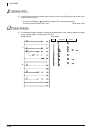
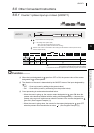
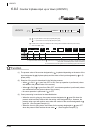
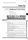
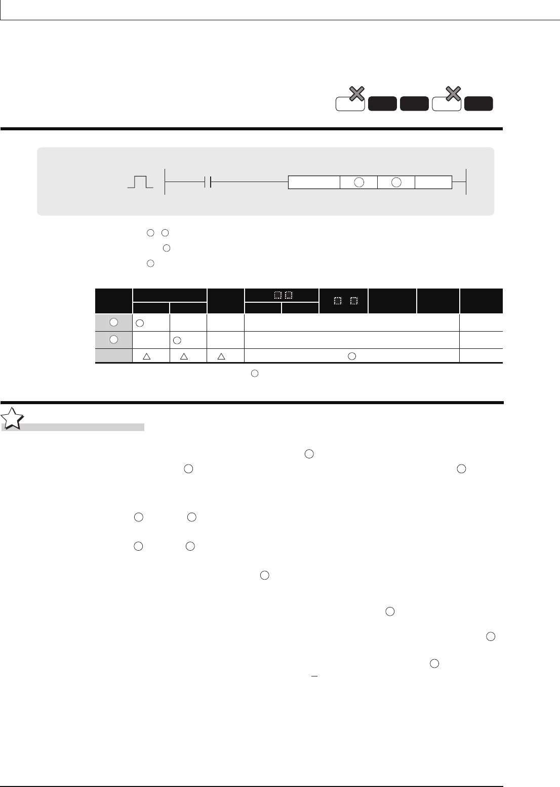
6.8.2 Counter 2-phase input up or down (UDCNT2)
UDCNT2
*1: Only the X device can be used for . However, the X device can be used only in the range of number of I/O points
(the number of accessible points to actual I/O modules).
*2: Local devices and the file registers set for individual programs cannot be used.
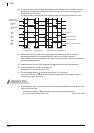
Function
(1) The present value of the counter designated by is updated depending on the status of the
input designated by (A phase pulse) and the status of the input designated by +1 (B
phase pulse).
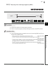
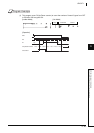
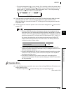
(2) Direction of the count is determined in the following manner:
• When is ON, if +1 goes from OFF to ON, count up operation is performed (values
are added to the present value of the counter).
• When is ON, if +1 goes from ON to OFF, count down operation is performed (values
are subtracted from the present value of the counter).
• No count operation is performed if is OFF.
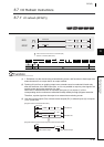
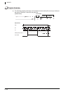
(3) Count processing is conducted as described below:
• When the count is going up, the counter contact designated at goes ON when the
present value becomes identical with the setting value designated by n. However, the
present value count will continue even when the contact of the counter designated at
goes ON. (See Program Example (1))
• When the count is going down, the counter for the contact designated at goes OFF
when the present value reaches the set value 1. (See Program Example (1))
: + 0: Input number for count input (A phase pulse) (bits)
+ 1: Input number for count input (B phase pulse) (bits)
: Number of the counter to be enabled to start counting with the UDCNT2 instruction (Device name)
n : Value to set (BIN 16 bits)
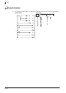
Setting
Data
Internal Devices
R, ZR
J\
U\G
Zn
Constants
K, H
Other
Bit Word Bit Word
(Only X)*1
–– –– –– ––
––
*1(Only C)
–– –– ––
n
*2 *2 *2
––
Process
High
performance
Universal
Basic
Redundant
Command
UDCNT2
n
UDCNT2 S D
S S
S
D
S
D
S
D
S S
S S
S S
S
D
D
D