


Special offers from our partners!

Find Replacement BBQ Parts for 20,308 Models. Repair your BBQ today.
App-159
8
8
8
8
A
8
7
8
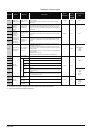
Appendix 4 SPECIAL REGISTER LIST
(2) System information
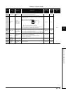
TableApp.4.4 Special register
Number Name Meaning Explanation
Set by
(When Set)
Corres-
ponding
ACPU
D9
Corresponding
CPU
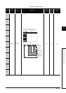
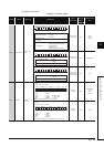
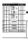
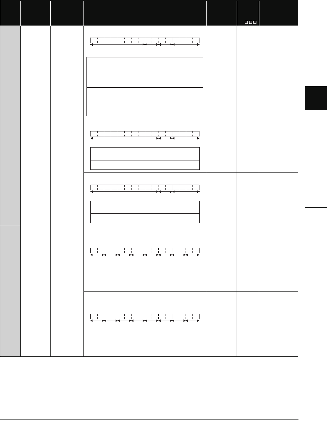
SD200 Status of switch
Status of CPU
switch
• The CPU switch status is stored in the following format:
S (Every END
processing)
New
Qn(H)
QnPH
QnPRH
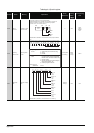
• The CPU switch status is stored in the following format:
S (Every END
processing)
New Q00J/Q00/Q01
• The CPU switch status is stored in the following format:
S (when RUN/
STOP/RESET
switch changed)
New QnU
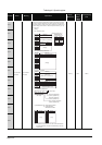
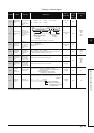
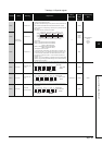
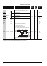
SD201 LED status
Status of
CPU-LED
• The following bit patterns store the status of the LEDs on the CPU
module:
• 0 is off, 1 is on, and 2 is flicker.
1): RUN 5): BOOT
2): ERR. 6): Empty Mode bit pattern
3): USER 7): Empty 0: OFF 1: Green
4): BAT. 8): MODE 2: Orange
(The Basic model QCPU does not include 3) to 8).)
S (Status
change)
New
Q00J/Q00/Q01
Qn(H)
QnPH
QnPRH
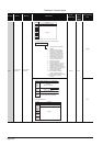
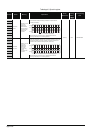
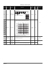
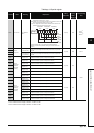
• The following bit patterns store the status of the LEDs on the CPU
module:
• 0 is off, 1 is on, and 2 is flicker.
1): RUN 5): BOOT
2): ERROR 6): Empty
3): USER 7): Empty
4): BAT. 8): MODE
(The Q00UJCPU, Q00UCPU, and Q01UCPU do not include 5).)
S (Status
change)
New QnU
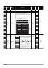
b15 b12 b11 b8 b7 b4 b3 b0
1)
2)
Empty
3)
to tototo
1): CPU switch status
0: RUN
1: STOP
2: L.CLR
2): Memory card
switch
Always OFF
3): DIP switch
b8 through b12 correspond to
SW1 through SW5 of system
setting switch 1.
0: OFF, 1: ON.
b13 through b15 are empty.
b15 b
8
b7 b4 b3 b0
1)2)
Empty
to to
to
1): 0: RUN
1: STOP
2):
CPU switch status
Memory card switch Always OFF
b15 b
8
b7 b4 b3 b0
1)2)
Empty
to to
to
1): 0: RUN
1: STOP
2):
CPU switch status
Memory card switch Always OFF
b15 b12b11 b8 b7 b4b3 b0
1)2)4) 3)5)6)8)7)
to tototo
b15 b12b11 b8 b7 b4b3 b0
1)2)4) 3)5)6)8)7)
to tototo