


Special offers from our partners!

Find Replacement BBQ Parts for 20,308 Models. Repair your BBQ today.
10-8
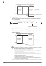
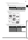
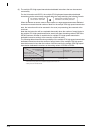
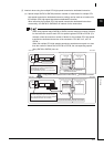
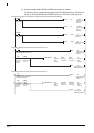
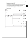
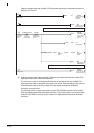
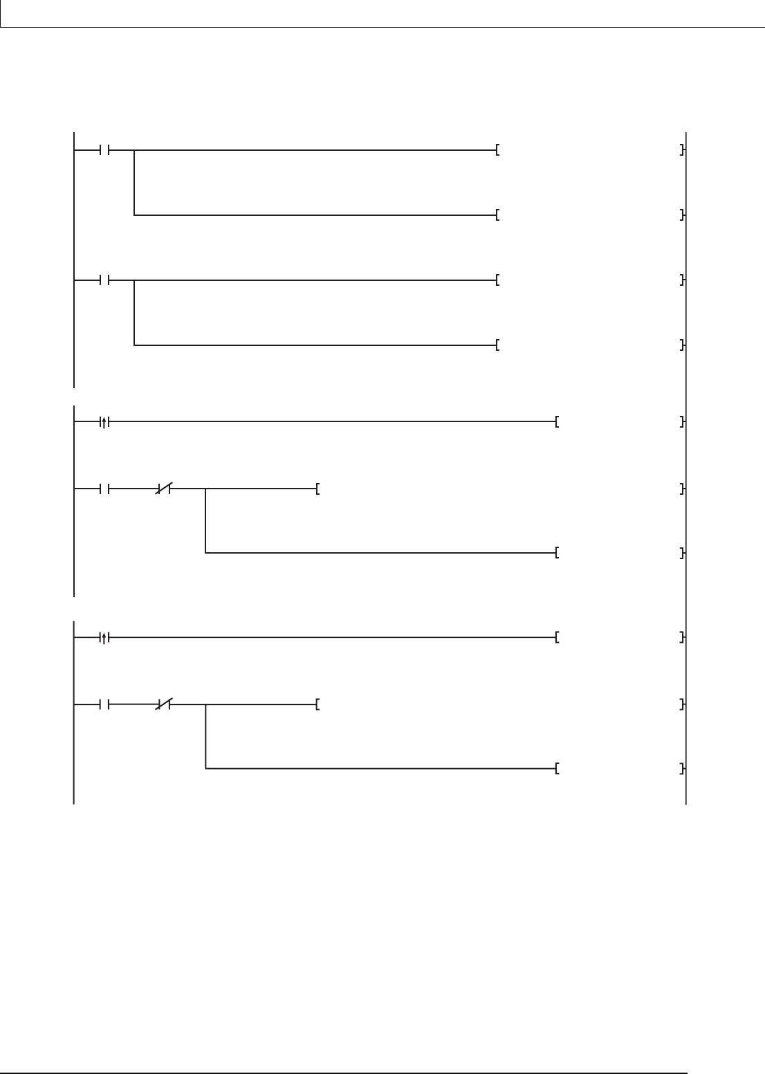
(b) Program example when SM796 to SM799 are used as an interlock
The following shows a program that executes the D.DDWR instruction to CPU No.2 at
the rise of X0, and executes the D.DDWR instruction to CPU No.3 at the rise of X1.
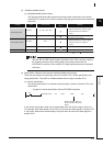
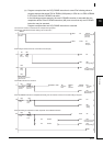
The maximum number of used blocks for multiple CPU hight speed transmission dedicated
SM402
SM402
0
8
Turn-on for one
scan after RUN
Turn-on for one
scan after RUN
MOV K7 SD797
Maximum number of
used blocks
(CPU No.2)
MOV K7 SD798
Maximum number of
used blocks
(CPU No.3)
MOV K100 D1
Mumber of write points
to CPU No.2
MOV K100 D3
Mumber of write points
to CPU No.3
The DDWR instruction is executed to CPU No.2 at the rise of X0
X0
11
Execution command of the
DDWR instruction to CPU No.2
14
M0 SM797
During execution
of the DDWR
instruction to
CPU No.3
Number of used
blocks information
(CPU No.2)
SET M0
During execution the
DDWR instruction to
CPU No.3
D.DDWRH3E1 D0 ZR0 ZR0 M1
Completion
status
(CPU No.2)
Write data
to CPU No.2
Write data
to CPU No.2
Completion
devaice
(CPU No.2)
RST M0
During execution of the
DDWR instruction to CPU No.2
The DDWR instruction is executed to CPU No.3 at the rise of X1
X1
29
During execution of the DDWR
instruction to CPU No.3
32
M3 SM798
During execution
of the DDWR
instruction to
CPU No.3
Number of used
blocks information
(CPU No.3)
SET M3
During execution the
DDWR instruction to
CPU No.3
D.DDWRH3E2 D2 ZR1000 ZR1000 M4
Completion
status
(CPU No.3)
Write data
to CPU No.3
Write data
to CPU No.3
Completion
device
(CPU No.3)
RST M3
During execution of the
DDWR instruction to CPU No.3