


Special offers from our partners!

Find Replacement BBQ Parts for 20,308 Models. Repair your BBQ today.
7DQGEHUJ'DWD &RQILJXULQJ,QVWDOOLQJDQG2SHUDWLQJWKH7DSH6\VWHP
7DQGEHUJ'/73URGXFW0DQXDO
&RQQHFWLQJ6&6,%XVDQG3RZHU&DEOHV
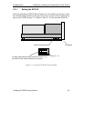
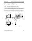
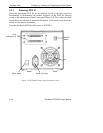
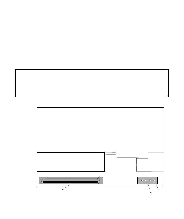
Carefully connect the appropriate SCSI and power cables to their matching
connectors.
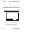
Figure 2-5 shows the location of the SCSI and power connectors on the rear of the
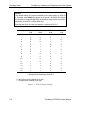
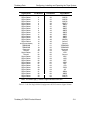
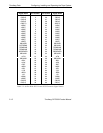
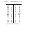
tape system. Tables 2-2 through 2-4 provide SCSI pin signal names/locations for
the SCSI connectors. Table 2-5 provides power connector signal names/locations.
127(
In some installations, it may be easier to connect the SCSI bus and power
cables before securing the tape system in its bay or position within its
cabinet or chassis.
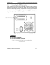
)LJXUH±&RQQHFWRUVIRU6&6,%XV&DEOHDQG3RZHU&DEOH
5HDU9LHZ&RQQHFWRU(QGRI7DSH6\VWHP
68-Pin SCSI Connector
Power Connector
Pin 1
Pin 1