


Special offers from our partners!

Find Replacement BBQ Parts for 20,308 Models. Repair your BBQ today.
7DQGEHUJ'DWD &RQILJXULQJ,QVWDOOLQJDQG2SHUDWLQJWKH7DSH6\VWHP
7DQGEHUJ'/73URGXFW0DQXDO
,QVWDOOLQJWKH7DSH6\VWHP
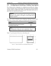
Installing the tape system requires securing the tape system in its bay or chassis
and connecting SCSI bus and power cables.
6HFXULQJWKH7DSH6\VWHPLQ%D\RU&KDVVLV
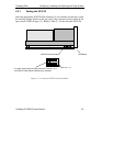
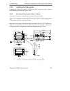
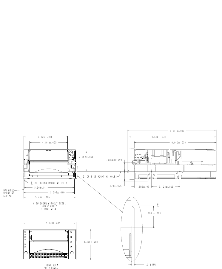
Using four (4) screws, secure the tape system in its bay or chassis.
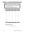
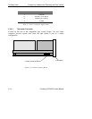
Figure 2-4 is a dimensional drawing that shows the locations of the mounting holes
at the bottom and sides of the tape system.
Note that screws used to mount the tape system must be #6-32 UNC-2B screws.
When the recommended size screws are used, there is no danger of the screws
touching electronic components or otherwise damaging the tape system.
)LJXUH±/RFDWLRQVDQG'LPHQVLRQVIRU0RXQWLQJ+ROHV