


Special offers from our partners!

Find Replacement BBQ Parts for 20,308 Models. Repair your BBQ today.

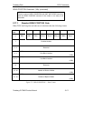
7DQGEHUJ'DWD 6&6,&RPPDQGV
7DQGEHUJ'/73URGXFW0DQXDO
5($'%8))(5&RPPDQG&KFRQWLQXHG
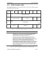
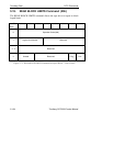
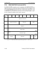
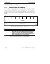
)LHOG1DPH 'HVFULSWLRQ
Mode The tape drive supports the following values within this field. If any
non-supported value is set, the drive terminates the command with a
CHECK CONDITION status, ILLEGAL REQUEST sense key set.
0RGH 'HVFULSWLRQ
000b Combined Header and Data (see 5.16.1)
010b Data (see 5.16.2)
011b Descriptor (see 5.16.3)
Buffer ID Must be 0, 1, or 2.
Buffer 0: This 1100 KB buffer is intended to be used in conjunction
with the WRITE BUFFER command to provide a diagnostic
capability for testing the SCSI bus and/or hardware
integrity.
Buffer 1: Choosing Buffer 1 results in the tape system transferring
the contents of controlled scratchpad RAM and EEPROM
over the SCSI bus. For DLT8000 tape systems, a total of
264K is transferred (256K for RAM, 8K for EEPROM).
Buffer 2: Choosing Buffer 2 results in the tape system transferring
the contents of data cache RAM over the SCSI bus. For
DLT8000 tape systems, a total of 8 MB is transferred.
Buffer Offset The Buffer Offset field allows the host to specify where the start of
the data is within the buffer.
Allocation Length This field specifies the maximum number of bytes that the initiator
has allocated for returning data. The host uses this field to limit the
size of data transfers to its own internal buffer size.
7DEOH±5($'%8))(5&RPPDQG'HVFULSWRU%ORFN²)LHOG'HVFULSWLRQV
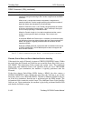
The host should first send a READ BUFFER command, in Descriptor mode, to
determine the size of the buffer being returned. In response to the READ BUFFER
command, the tape system returns four bytes of data, three of which contain the
size of the buffer. The host can then use this data to establish the Buffer
Offset/Allocation Length fields of the CDB. Once the size of the buffer is known,
Mode 2 (Data Only, see Section 5.16.2) can be used to transfer the data across the
SCSI Bus.