


Special offers from our partners!

Find Replacement BBQ Parts for 20,308 Models. Repair your BBQ today.

7DQGEHUJ'DWD 6&6,&RPPDQGV
7DQGEHUJ'/73URGXFW0DQXDO
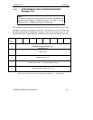
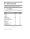
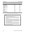
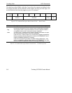
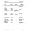
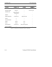
Operation Code The operation code specifies the command being requested. The list
of supported SCSI commands and their operation codes are contained
in Table 5–1.
Logical Unit Number The Logical Unit Number contains the number of the device being
addressed. It must be set to 0. The Logical Unit Number is ignored if
the Command Descriptor Block is preceded by an IDENTIFY
Message.
Logical Block Address Commands that require additional parameter data specify the length of
the Logical Block Address that is needed. See the specific command
descriptions for more detailed information.
The drive does not support Relative Addressing: it defaults to a value
of 0 which specifies that the Logical Block Address specifies the first
logical block of a range of logical blocks to be operated on by the
command. Relative Addressing indicates a technique used to
determine the next Logical Block Address to be operated on.,
Transfer Length The transfer length field normally specifies the number of blocks to be
transferred between the initiator and the drive. For several commands,
the transfer length indicates the number of bytes (not blocks) to be
sent. For these commands, this field may be identified by a different
name.
Parameter List Length
The Parameter List Length is used to specify the number of bytes sent
during the DATA OUT phase. This field is typically used for parameters
that are sent to a drive (for example, mode, diagnostic, and log
parameters). A parameter list length of 0 indicates that no data is to be
transferred.
Allocation Length
This field specifies the maximum number of bytes that the initiator has
allocated for returning data. The host uses this field to limit the size of
data transfers to its own internal buffer size.
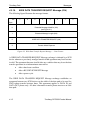
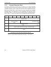
Control Field
The Control Field is the last byte of every command descriptor block.
Its format is shown in Figure 5–2, and it contains the Flag and Link
bits. Use of these bits is initiator-dependent. Setting the Link bit = 1
provides an automatic link to the next command, bypassing the usual
ARBITRATION, SELECTION, and MESSAGE OUT phases that would
normally occur between commands. Other bits in the Control Field are
considered to be reserved.
Relative Address
(RelAdr)
Must be 0 (not supported).
7DEOH±&RPPDQG'HVFULSWRU%ORFN²)LHOG'HVFULSWLRQV