


Special offers from our partners!

Find Replacement BBQ Parts for 20,308 Models. Repair your BBQ today.

A-2 Dell PowerEdge Cluster FE100 Installation and Troubleshooting Guide
&KHFNLQJ<RXU ([LVWLQJ+D UGZDUH
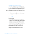
Before you can upgrade your system, you must ensure that your existing hardware
meets the minimum configuration requirements for the PowerEdge Cluster FE100.
See “Minimum System Requirements” in Chapter 1 for a list of the components and
minimum system configuration required for the PowerEdge Cluster FE100. You can
skip any part of the upgrade procedure that has already been performed on your sys-
tem in a previous configuration.
NOTE: To upgrade your systems from Windows NT Server to include the Enterprise
Edition functionality, you must completely install the Windows NT Server, Enterprise
Edition operating system.
Contact your Dell sales representative for information on acquiring the related hard-
ware components and customer kits that you need for the upgrade.
See “Basic Installation Procedure” in Chapter 1 for the full procedure that you must
perform to upgrade existing PowerEdge 6300, 6350, and 4300 systems and a Power-
Vault 65
x
F storage system to a PowerEdge Cluster FE100.
$GGLQJ([SDQVLRQ&DUGVIRUD&OXVWHU
8S JUDGH
Dell has tested and determined that the following guidelines provide the optimal node
configurations for clustering:
For PowerEdge 6300 and 6350 servers:
To balance the Peripheral Component
Interconnect (PCI) busses and to achieve the highest availabilty, Dell recom-
mends that you place one QLogic host bus adapter in an available 32-bit slot and
one adapter in an available 64-bit slot. If you are using a Dell Remote Access Card
(DRAC II), place it in PCI slot 3. If you are using an Adaptec 6922 Duralink NIC,
place it in any available 64-bit PCI slot.
For PowerEdge 4300 servers:
Dell recommends placing one QLogic host bus
adapter in an available slot in front of the PCI bridge (PCI slots 1 through 4) and one
adapter in an available slot behind the bridge (PCI slots 5 and 6). If you are using a
DRAC II, place it in PCI slot 4. If you are using a Dell PowerEdge Expandable RAID
Controller, place it in an available slot behind the bridge (PCI slot 5 or 6).
For the latest information on PCI slot guidelines, refer to Dell's Web site at
www.dell.com.
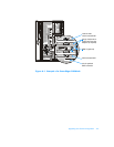
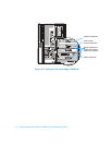
Figures A-1 and A-2 show the back views of nodes with example configurations. Fig-
ure A-1 shows a PowerEdge 6300 node (the same configuration applies to
PowerEdge 6350 nodes); Figure A-2 shows a PowerEdge 4300 node.