


Special offers from our partners!

Find Replacement BBQ Parts for 20,308 Models. Repair your BBQ today.
1-2 Dell PowerEdge Cluster FE100 Installation and Troubleshooting Guide
3 RZHU(GJH & OXVWHU )( &R PSRQHQWV
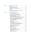
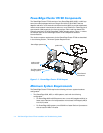
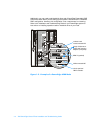
The PowerEdge Cluster FE100 consists of two PowerEdge 6300, 6350, or 4300 sys-
tems (the nodes) equipped with two QLogic QLA-2100 or QLA-2100F host bus
adapters and two or more network interface controllers (NICs) to provide a dedicated,
node-to-node network interconnection and one or more Ethernet or Token-Ring local
area network (LAN) segments for client connections. Each node has shared Fibre
Channel connections to a Dell PowerVault™ 65
x
F storage system. Figure 1-1 shows
an example layout of the PowerEdge Cluster FE100 components and their
interconnections.
The minimum system requirements for the PowerEdge Cluster FE100 are described
in the following section, “Minimum System Requirements.”
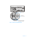
)LJXUH3RZHU(GJH&OXVWHU)(/D\RXW
0LQLPXP6\VWHP5HTXLUHPHQWV
The PowerEdge Cluster FE100 requires the following minimum system hardware
configuration:
Two PowerEdge 6300, 6350, or 4300 systems, each with the following
configuration:
— For PowerEdge 6300 or 6350 systems, two or more 400-megahertz (MHz) or
faster Intel
®
Pentium
®
II microprocessors with at least 512 kilobytes (KB) of
level 2 (L2) cache
— For PowerEdge 4300 systems, two 350-MHz or faster Pentium II processors
with at least 512 KB of L2 cache
PowerEdge systems (2)
Dell PowerVault 65xF
storage system
node-to-node
interconnect
public LAN
Fibre Channel
connections