


Special offers from our partners!

Find Replacement BBQ Parts for 20,308 Models. Repair your BBQ today.

2-4 Dell PowerEdge Cluster FE100 Installation and Troubleshooting Guide
([SDQGLQJWKH3RZHU9DXOW[)6WRUDJH6\VWHP
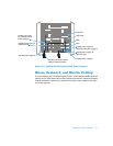
You can expand PowerVault 65
x
F Disk-Array Processor Enclosures (DPEs) by adding
PowerVault 630F DAEs to the system. The DAEs are connected to the DPE using
0.3-m cables with DB-9–to–DB-9 connectors. Use the following procedure to cable
additional DAEs to the PowerVault DPE or daisy-chain DAEs to other DAEs:
1. Connect one end of the 0.3-m copper cable to the connector labeled “EXP” on
an LCC in the DPE or DAE.
2. Tighten the two thumbscrews on the cable’s connector.
3. Connect the other end of the copper cable to the primary connector labeled
“PRI” on the adjacent LCC in the PowerVault DAE.
NOTE: LCC A and LCC B are located on opposite ends of the DPE or DAE. Connect
only LCC A cards with other LCC A cards and LCC B cards with other LCC B cards. Do
not connect a cable between an LCC A and LCC B cards.
4. Tighten the two screws on the cable’s connector.
For additional instructions, see Chapter 2 of the
Installation and Service Guide
for your
PowerVault storage system.
1,&&DEOLQJ
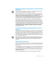
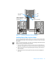
The NICs in the PowerEdge systems provide two network connections on each
node—a dedicated network interconnection between the nodes and a connection to
the local area network (LAN). Having two network interconnections from each Power-
Edge system can provide redundancy at the communications level in the event that
one of the cluster NICs fails. The node-to-node connection is established using a
crossover Category 5 unshielded twisted pair (UTP) cable. A crossover cable allows
you to connect two NICs to each other without using a network switch.
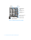
Figure 2-2 shows a sample configuration of NIC cabling where dedicated NICs in each
node are connected to one another with the crossover cable to form the private node-
to-node interconnection. Connection to the public LAN is provided by a second NIC in
each node using a standard, unshielded Category 5 cable.