


Special offers from our partners!

Find Replacement BBQ Parts for 20,308 Models. Repair your BBQ today.

Liebert iCOM
®
Control
Liebert
®
CRV
™
82
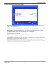
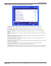
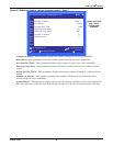
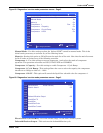
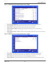
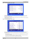
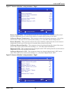
Figure 71 Diagnostics / service mode parameters screen - Page 5
Status Remote Shutdown—This show the status of the unit’s remote shut down input.
Status Airflow 1 & 2—This show the status of the unit’s air proof switches.
Status Filter—This shows the status of the unit’s filter clog switch input.
Status Customer Input 1, 2, 3 & 4—This shows the status of the unit’s customer inputs.
Status LSI—
Status Heaters Safety—(HPM and PEX only) This parameter shows the status of the unit’s reheat
safety switch.
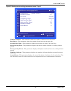
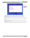
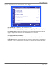
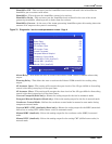
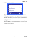
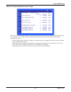
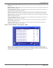
Figure 72 Diagnostics / service mode parameters screen - Page 6
Status HP1—This shows the status of the unit’s compressor 1 high pressure switch input.
Status LP1—This shows the status of the unit’s compressor 1 low pressure switch input.
Status LWD—This shows the status of the unit’s Leakage Water Detector.
Status Liquitech—This shows the status of the unit’s Liebert Liqui-tect
®
liquid detection setup.
to change parameter
for next/previous unit
to select parameter
to confirm
then
S345
S346
S347
S348
S349
S350
S351
S352
S353
S354
S355
PASSWORD Actual Level 0) ????
Status Remote Shutdown o-o On
Status Airflow 1 o-o OK
Status Airflow 2 o-o OK
Status Filter o-o OK
Status Customer Input 1 o/o OK
Status Customer Input 2 o/o OK
Status Customer Input 3 o/o OK
Status Customer Input 4 o/o OK
Status LSI o-o OK
Status Heaters Safety o/o Act
DIAGNOSTICS/SERVICE MODE (page 5 of 6) UNIT 01
to change parameter
for next/previous unit
to select parameter
to confirm
then
S356
S357
S358
S359
S360
S361
S362
S363
S364
S365
S366
PASSWORD Actual Level 0) ????
Status HP1 o/o OK
Status LP 1 o-o OK
Status LWD %
Status Liquitech
DIAGNOSTICS/SERVICE MODE (page 6 of 6) UNIT 01