


Special offers from our partners!

Find Replacement BBQ Parts for 20,308 Models. Repair your BBQ today.

Liebert iCOM
®
Control
93 Liebert
®
CRV
™
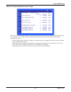
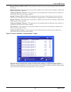
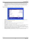
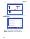
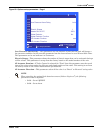
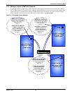
Figure 87 Rack Setup, Page 2
The Rack Setup display allows creating a graphical map of the remote rack sensors.
When the Assigned Sensors 1-6 are selected, it will drop the user down to assign the sensor node
address to the first group of six “boxes.” Setting “CRV” instead of a number (CRV is located below 0)
will give the hard-coded name “CRV” to the selected box.
A sensor address (#1- #10) or “CRV” can be assigned only once per screen.
The names for each rack can be assigned on the next page. Once names have been assigned, they will
also show up on this page (read only).
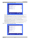
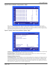
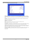
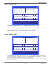
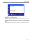
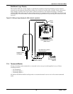
Figure 88 Rack Setup, Page 3
The Rack Setup display allows naming each rack with up to four characters, either letters or digits
(A-Z or 0-9). Names can be assigned to each rack except those that have no sensor (#0-#10), no “CRV”
or “Rack w/o sensor (-2)” assigned on the previous Rack Setup page.
When the Assigned Names 1-6 are selected, it will drop the user down to assign the rack name to the
first group of six “boxes.”
Use the navigation keys to move from rack to rack.
Enter to select a rack, and up- or down keys to scroll through
options .
RACK SETUP (page 2 of 3) UNIT 01
Liebert CRV = CRV
No Sensors = -2
No Rack = 0
Sensor Node = 01-10
Assign Sensors: 01-06
07-12
13-18
19-22
Cold Aisle
10000002340
05600000000
CC21
Use the navigation keys to move from rack to rack.
Enter to select a rack, and up- or down keys to scroll through
options .
RACK SETUP (page 3 of 3) UNIT 01
Liebert CRV = CRV
No Sensors = -2
No Rack = 0
Sensor Node = 01-10
Assign Sensors: 01-06
07-12
13-18
19-22
Cold Aisle
10000002340
05600000000
EC50 EC51
CC21 BB01 BB02BB03