


Special offers from our partners!

Find Replacement BBQ Parts for 20,308 Models. Repair your BBQ today.

Refrigeration and Hydraulic Circuits
Liebert
®
CRV
™
126
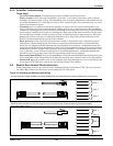
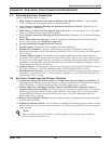
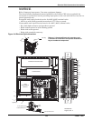
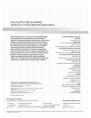
APPENDIX D-REFRIGERATION AND HYDRAULIC CIRCUITS
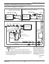
Figure 105 General arrangement—air-cooled units
Distributor
+
+
Suction Line
DPN001984
Rev. 4
Factory Refrigerant Piping
Field Piping
Outdoor VFD Condenser
Vibration
Absorber
Vibration Absorber
Check Valve
Low-Pressure Transducer
High-Pressure
Transducer
* Components are not supplied by
Liebert but are recommended for
proper circuit operation and
maintenance. Should be located
near the indoor Liebert CRV unit.
+ Inverted Trap on Discharge and
Liquid Lines to extend above the
base of the coil by a minimum of
7-1/2" (190mm).
Digital
Scroll
Compressor
1. Schematic representation shown. Do not use for specific connection locations.
2. One or more additional pressure relief valves are required downstream of any
and all field-installed isolation. Do not isolate any refrigerant circuits from
overpressurization protection.
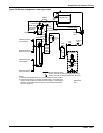
CR020 Digital
Solenoid Valve
Expansion
Valve
External Equalizer
CR035 Digital
Solenoid Valve
Hot Gas Discharge
Hot Gas Discharge
VFD Transducer
Sensing
Bulb
Optional Field-Installed
Fusible Plug
Service Valve
High-
Pressure
Cut Out
Condenser Coil
(VFD)
Solenoid
Valve
Sight
Glass
Filter
Drier
Service Valve
*Isolation Valve
*Isolation Valve
* Traps Every
15ft. (4.6m)
of Rise
Evaporator Coil
Liquid Return
Service / Schrader (Access) Connection With Valve Core
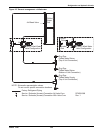
+
+
Outdoor Lee-Temp Condenser
Check Valve
Condenser Coil
(Liebert Lee-Temp)
Hot Gas Discharge
Relief Valve
Liquid
Return
Lee-Temp Receiver
Head Pressure
Control Valve
Service / Schrader (Access) Connection No Valve Core