


Special offers from our partners!

Find Replacement BBQ Parts for 20,308 Models. Repair your BBQ today.
Electrical Data
123 Liebert
®
CRV
™
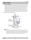
APPENDIX B-ELECTRICAL DATA
NOTICE
Risk of exceeding line-to-ground limit. Can cause equipment damage.
The electrically commutated (EC) motors included in 480V CR035 and CR040 units are
suitable for connection to power supplies with 300V or less line to ground potential. Excess
line-to-ground voltage can cause capacitor failure internal to the motors.
• Power supplies such as 480V WYE with solidly grounded neutral have 277V line to ground
and are acceptable.
• Power supplies such as 480V WYE with high resistance (or impedance) ground, 480V delta
without ground or with floating ground, 480V delta with corner ground or 480V delta with
grounded center tap will exceed the 300V line-to-ground limit.
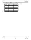
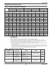
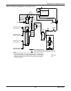
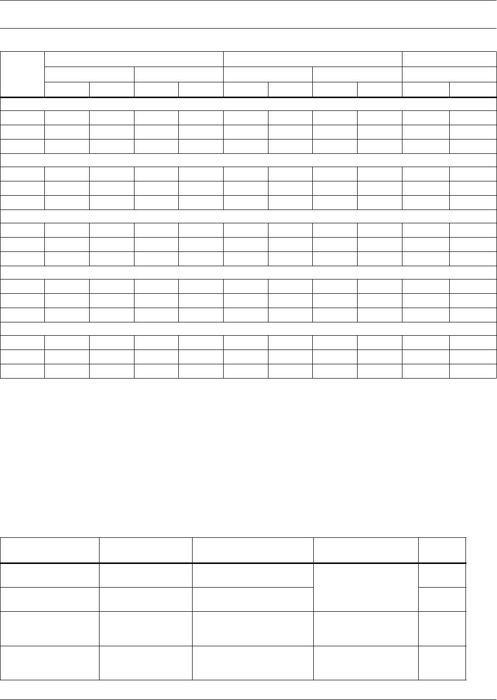
Table 32 Liebert CRV electrical data - 60Hz (Amps)
Voltage
Air-Cooled Units Water/Gylcol-Cooled Units Chilled Water Units
CR035RA CR020RA CR035RW CR020RW CR040RC
460/3/60 208/3/60 460/3/60 208/3/60 460/3/60 208/3/60 460/3/60 208/3/60 460/3/60 208/3/60
Cooling with Dehumidifying, Condensate Pump, Reheat; with or without Humidifier
FLA 31.7 62.0 24.3 51.0 31.7 62.0 24.3 51.0 11.7 24.9
WSA 38.6 75.4 29.3 61.6 38.6 75.4 29.3 61.6 14.6 31.1
OPD 50 100 35 80 50 100 35 80 20 35
Cooling with Dehumidifying, Condensate Pump and Humidifier; NO Reheat
FLA 27.9 53.8 20.5 42.8 27.9 53.8 20.5 42.8 7.9 16.7
WSA 32.9 63.1 23.6 49.3 32.9 63.1 23.6 49.3 9.9 20.9
OPD509035705090357015 25
Cooling with Dehumidifying and Condensate Pump, NO Reheat, NO Humidifier
FLA 24.2 45.4 16.8 34.4 24.2 45.4 16.8 34.4 4.2 8.3
WSA 29.2 54.7 19.9 40.9 29.2 54.7 19.9 40.9 4.6 9.1
OPD459030604590306015 15
Cooling with Dehumidifying and Reheat; NO Condensate Pump, NO Humidifier
FLA 30.5 59.7 23.1 48.7 30.5 59.7 23.1 48.7 10.5 22.6
WSA 37.4 73.1 28.1 59.3 37.4 73.1 28.1 59.3 13.1 28.3
OPD 50 100 35 80 50 100 35 80 15 30
Cooling with Dehumidifying, NO Condensate Pump, NO Reheat, NO Humidifier
FLA 23.0 43.1 15.6 32.1 23.0 43.1 15.6 32.1 3.0 6.0
WSA 28.0 52.4 18.7 38.6 28.0 52.4 18.7 38.6 3.4 6.8
OPD458030604580306015 15
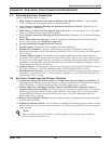
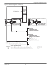
Table 33 Calibration of electrical components
Refrigeration Circuit
Item No. Component Setting Notes Contact
18-19
High Pressure
Transducer
Range 045 barg
Output 05V
See Liebert iCOM
®
User Manual, SL-18835
—
14
Low Pressure
Transducer
Range 017.3 barg
Output 05V
—
3
High Pressure
Switch (HP)
STOP 38.7±1 barg
START 30.0±1.5 barg
(fixed setting manual reset)
Reset
Normally
Closed
—
Clogged Filter
Differential Pressure
Switch (CF)
Setpoint range 0.54 mbar
Filter G4 = 2 mbar
Setting Ring
Normally
Closed