


Special offers from our partners!

Find Replacement BBQ Parts for 20,308 Models. Repair your BBQ today.

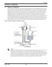
Humidifier
Liebert
®
CRV
™
120
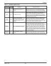
A.1.6 Humidifier Troubleshooting
Terms Used
• FLA (Full Load Amps) are amps listed on the humidifier specification label.
• Short cycling occurs when the humidifier’s “On time” is less than 10 minutes upon a call for
humidity. To correct short cycling, all humidifiers have a capacity adjustment that allows the out-
put of the humidifier to be reduced to as low as 20% of rated output, thus extending the “on time”
required to maintain output.
• Foaming can occur when the impurities already in water reach an excess concentration as a
result of boiling away water and continued boiling agitates the contained water. The humidifier
electronics are designed to prevent foaming, although in extreme cases water will foam with little
concentration, making it necessary to increase the drain time of the water contained in the cylin-
der. Foaming is normally caused by short cycling, a restricted drain or back pressure. The foam
generated in these instances is conductive and may lead to false full-cylinder indication if the
level of the foam approaches the top of the cylinder.
• Back pressure is the restriction of steam flow caused by long steam runs, improperly sloped
steam lines, elbows changing the direction of steam flow from horizontal to vertical without a
drain leg, any plumbing detail allowing the accumulation of condensate, undersized steam line,
improper steam distributor, downward air flow onto the distributor causing excess static pressure
at the steam outlets, or high static pressure ducts (not probable). To overcome excess static pres-
sure in the duct, use a fill cup extension kit. In downflow applications, a downflow distributor
should be used, but in some cases the fill cup extension will also be required.
• Reset unit (humidifier): To reset the humidifier, switch the auto On/Off/Drain switch at the front
of the humidifier to the Off position for at least five seconds, then switch it back to the On position.
• Monitored leg is the primary wire to the cylinder that loops through the current sensing device
of the main PCB. This wire ends at the red cylinder plug at the cylinder.
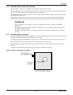
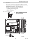
A.2 REMOTE RACK SENSOR TROUBLESHOOTING
If the sensor has been set up correctly and is communicating to the Liebert CRV, then the status of
the LED (DS1) located on the sensor circuit board will be solid green.
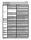
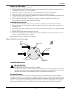
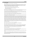
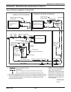
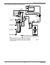
Figure 103 CAN bus and Ethernet cable wiring
Ethernet cable; suitable for U2U connection or for connecton of the Liebert iCOM Large Coldfire Display;
all through switch or hub
Six-wire CAN bus cable; suitable for Liebert iCOM board with THB, HCB and Liebert iCOM display connections
1
2
3
4
5
6
7
8
1
2
3
4
5
6
7
8
Pair 4
Pair 2
Pair 3
Pair 1
A
1
2
3
4
5
6
Pair 2
Pair 3
Pair 1
A
1
2
3
4
5
6