


Special offers from our partners!

Find Replacement BBQ Parts for 20,308 Models. Repair your BBQ today.

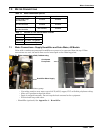
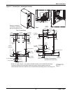
Water Connections
Liebert
®
CRV
™
36
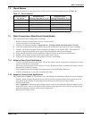
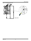
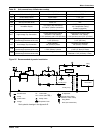
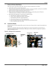
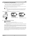
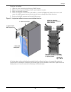
Figure 25 Recommended drycooler Installation
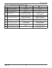
Table 20 Unit connections, chilled water models
Unit Connections CR040C (50 Hz) CR040C (60 Hz)
CWS Chilled Water Supply 32mm GAS F 1-1/4" FPT
CWR Chilled Water Return 32mm GAS F 1-1/4" FPT
GD Gravity Coil Pan Drain 20mm I.D. 1" MPT
GDH Gravity Humidifier Drain 22mm I.D. N/A
HS Humidifier Supply
1/2" GAS F (top connection)
3/4" GAS F (bottom connection)
1/2" FPT (top connection)
1/4" Compression Fitting
(bottom connection)
CP Condensate Pump 1/2" GAS F 1/2" FPT
HVT High Voltage Top Connection
Combination Knockout Hole
Diameter 1-3/8" (35mm)
1-3/4" (44.5mm) and 2-1/2" (63.5mm)
Combination Knockout Hole
Diameter 1-3/8" (35mm)
1-3/4" (44.5mm) and 2-1/2" (63.5mm)
HVB
High Voltage Bottom Entrance
(feed through the base of the unit)
Hole Diameter
2-1/2" (63.5mm)
Knockout Hole Diameter
2-1/2" (63.5mm)
LVT Low Voltage Top Connection
Hole Diameter
7/8" (22mm) 2 places
Knockout Hole Diameter
7/8" (22mm) 4 Places
LVB
Low Voltage Bottom Entrance
(feed through the base of the unit)
Hole Diameter
1-7/64" (28mm) 2 places
Knockout Hole Diameter
1-3/32" (27.8mm) 2 Places
LVB2
Low Voltage Bottom Entrance
(feed through the base of the unit)
—
Combination Knockout Hole
Diameter 1-3/4" (44.5mm) 1 Place
Source: DPN001794, Rev. 2
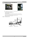
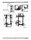
APPLIANCE
TSHTC
Filling
Water
(optional)
HTC
TS
Shutoff Valve
Pump
Check Valve
Gauge
Thermostat
Variex (50Hz Opt.)
Safety Valve
Expansion Tank
Air Separator
Charge Group (Filter,
Reducer, Check Valve)
Filling Meter
Drain (at Lowest Point)
(*)
Standby Pump
Standby Pump
Pressure-Operated Bypass
See hydraulic drawings in the Appendix D
Disconnect
After Charge