


Special offers from our partners!

Find Replacement BBQ Parts for 20,308 Models. Repair your BBQ today.

Liebert iCOM
®
Control
Liebert
®
CRV
™
66
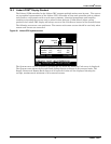
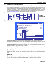
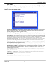
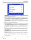
View Network
View Network—The view network screen provides an overview of the Liebert iCOM
®
network and a
status of each unit. This screen will provide the unique unit name given to the unit. If no name is
given, then only the unit number will be displayed.
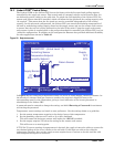
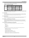
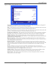
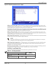
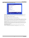
Figure 53 Sensor data parameters screen
Temperature Setpoint—This parameter shows the cooling setpoint, which is the setpoint used to
drive the compressor capacity. This parameter will automatically change based on which sensor is
used for control (Return, Supply or Remote sensor).
Actual Control Temperature—This parameter is the temperature reading of the actual sensor
that is referenced to U301. This parameter automatically changes based on the control sensor setting.
Fan Setpoint—This parameter defines the fan speed setpoint. This value is not shown when a single
sensor (Coupled Mode) is used to control cooling capacity and fan speed. This parameter is calculated
by adding the temperature setpoint and the fan speed delta in the Service / Setpoints menu.
Actual Fan Control Temp—This parameter is the temperature reading of the actual sensor that is
referenced to U303. This parameter automatically changes based on the control sensor settings.
Humidity Setpoint—This parameter allows the user to select a humidity that the cooling unit will
maintain by removing or adding moisture to the air. This parameter is adjustable from 20-80%. The
factory default setting from the factory is 50%.
Actual Return Humidity—This parameter is the return relative humidity reading of the sensor.
Actual Supply Humidity—This parameter is the calculated relative humidity of the supply sensor
based on the actual return humidity reading. This value is calculated by using a reverse look up
algorithm based on dew point.
Actual CW Temperature—This parameter displays the actual chilled water supply temperature
being delivered to the unit.
DigiScroll 1 Temperature—When digital scroll compressors are installed in the unit then the
actual digital scroll number 1 head temperature will be shown.
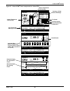
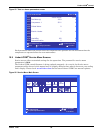
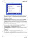
Active Alarms
Active Alarms—Permits viewing all current, active alarms.
This window is READ ONLY
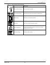
U301
U302
U303
U304
U305
U306
U307
U308
U309
U310
U311
U312
Temperature Setpoint °F
Actual Control Temperature °F
Fan Setpoint °F
Actual Fan Control Temp °F
Humidity Setpoint %
Actual Return Humidity %
Actual Supply Humidity %
Actual CW Temperature °F
DigiScroll 1 Temperature °F
SENSOR DATA UNIT 01