


Special offers from our partners!

Find Replacement BBQ Parts for 20,308 Models. Repair your BBQ today.
Refrigerant Connections
27 Liebert
®
CRV
™
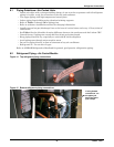
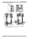
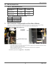
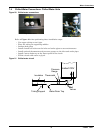
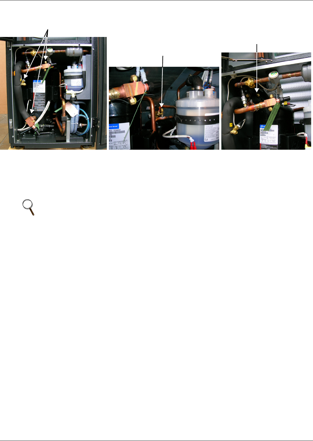
Figure 18 Connections for vacuum creation and refrigerant charge
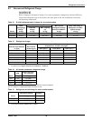
6.3.1 Evacuation Air-Cooled Models
Variable Fan Speed Control Leak Check and Evacuation Procedure
Proper leak check and evacuation can be accomplished only with all system solenoid valves open and
check valves accounted for.
1. If unit power is available, open the unit liquid line solenoid valves using the evacuation function
for System #1 in the diagnostic section of the Liebert iCOM
®
control (see Figure 68). If unit
power is not available, a field-supplied 24VAC / 75VA power source must be directly connected to
the unit solenoid valve.
2. Connect refrigerant gauges to the suction rotalock valves and discharge line Schrader valves.
3. Open the service valves and place a 150 PSIG (1034 kPa) of dry nitrogen with a tracer of
refrigerant. Check system for leaks with a suitable leak detector.
4. After completion of leak testing, release the test pressure (per local code) and pull an initial deep
vacuum on the system with a suitable pump.
5. After four hours, check the pressure readings and, if they have not changed, break vacuum with
dry nitrogen. Pull a second and third vacuum to 250 microns or less. Recheck the pressure after
two hours. After completing this step, proceed to Variable Fan Speed Charging on page 28.
NOTE
The system include a factory-installed check valve and an additional downstream Schrader
valve with core in the compressor discharge line. Proper evacuation of the condenser side of the
compressor can be accomplished only using the downstream Schrader valve. See piping
schematic.
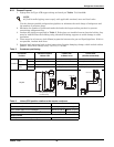
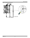
Suction and Supply Line Connections
Liquid Line Connection
Thermostatic Valve Connection