


Special offers from our partners!

Find Replacement BBQ Parts for 20,308 Models. Repair your BBQ today.

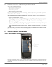
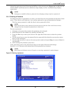
Startup
47 Liebert
®
CRV
™
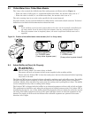
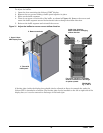
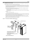
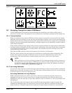
Figure 36 Termination jumper setting
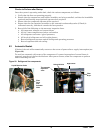
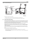
9.5.4 Route the CAN bus wire into the cooling unit
The CAN bus sensors connect to the open CAN port on the back of the unit display panel. The Display
comes “Terminated” from the factory and will have to be “Un-terminated’ to allow for additional
sensors to be added. See photo above for termination jumper location for front panel display and
sensor boards. Note that connecting the CAN bus sensors will require entering the High Voltage
electrical compartment of the Liebert CRV. If you are not comfortable with the installation procedure,
it is recommended that you hire a certified electrician.
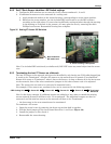
Connect the 10ft CAN wire to the open CAN bus port on the rear of the iCOM graphic display.
Ensure there is enough slack in the wire to allow the door to open and close freely, but not too much
slack to bind or pinch when the door is shut. It is recommended that a cable tie is used to secure the
wiring.
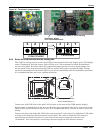
Connect the other end of the 10ft CAN cable to the nearest 2T rack sensor. Use additional CAN cables
to connect the remaining 2T rack sensors to each other. The order in which the 2T sensors are
attached does not matter; however, be sure that the last sensor connected is the one set to
“terminated”. As a best practice, avoid using excessive lengths of cable between sensors.
Unterminated
Terminated
321 321
Termination Jumper
in the Terminated Position
Circuit board inside display housing Circuit board inside 2T sensor housing
Rear of Large Graphic Display
Source DPN001983 Rev. 0
Inside of Display Door
CAN CAN
SW/U2U12VDC PWR