


Special offers from our partners!

Find Replacement BBQ Parts for 20,308 Models. Repair your BBQ today.

Liebert iCOM
®
Control
61 Liebert
®
CRV
™
10.3 Liebert iCOM
®
Control Setup
The Liebert iCOM on the Liebert CRV leaves the factory with the fan speed and cooling capacity
controlled by the supply air sensor. This control mode is extremely robust and will ensure that you
are delivering precise cooling to the cold aisle. To unlock the full capability of the Liebert CRV, the
remote rack sensors should be installed, which will allow the fan speed and the cooling capacity to be
“de-coupled.” This means that the fan speed can now be controlled independently of the cooling
capacity. In this advanced configuration, the Liebert CRV can control the discharge temperature of
the unit by modulating cooling capacity based on the supply sensor and use the remote rack sensors
to ensure that the cool air is being delivered to the inlet of the racks. Using the supply and remote
rack sensors in this de-coupled mode is the preferred method for controlling the Liebert CRV in a hot
/ cold aisle configuration. In addition to this configuration Emerson has provided additional flexibility
for other applications shown in Table 25.
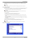
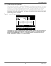
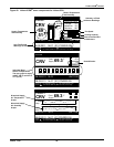
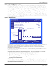
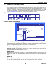
Figure 50 Setpoint screen
In Figure 50, the controlling temperature sensor can be set to either Supply, Return or Remote. As
the selection is changed from one sensor to another, the setpoint is displayed next to the
corresponding sensor on the illustration, giving a visual indication of the sensor placement in
relationship to the Liebert CRV.
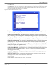
A password must be entered to change the setting; see 10.1.3 Entering a Password for assistance
on entering the password.
Temperature sensor settings are based on user preference. Use the settings below as a guideline.
1. Set the remote temperature setpoint to the desired server inlet temperature
2. Set the humidity setpoint to 45% with a 10 to 20% deadband.
This will control the moisture content well inside the AHSRAE standard.
3. Set the supply setpoint 5°F below the setting for the remote rack sensor.
This will serve as a starting point.
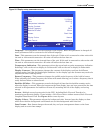
If 75°F (24°C) server entering air temperature is desired, the supply air must be colder to account for
any thermal pickup of the air as it flows to the cold aisle. If this does not achieve the cold aisle
temperature Setpoint, then set the supply sensor setpoint lower. Continue to do this until the cold
aisle temperature setpoint is achieved.
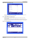
SETPOINTS UNIT 02
U101
U102
U103
U104
PASSWORD (Actual Level 0)
Controlling Sensor
Temperature Setpoint
Humidity Setpoint
????
Supply
70°F
50%
for next/previous unit
then
Supply Sensor
Return Sensor
Remote Sensor
to change parameter
70°
50%
to select parameter
to confirm