


Special offers from our partners!

Find Replacement BBQ Parts for 20,308 Models. Repair your BBQ today.

Humidifier
121 Liebert
®
CRV
™
A.3 STARTING POINT
Auto On/Off/Drain switch in On position—unit will not fill:
When the On/Off control circuit is made and the Auto On/Off/Drain switch is pushed to On, the 24V
holding coil of the primary contactor should energize. The resulting magnetic pull closes the high
voltage contacts with a distinct and audible “clunk.” If the contactor will not make the connection,
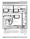
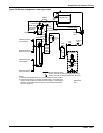
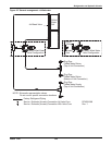
then inspect the following while referring to the wiring diagram:
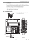
• Check for 24V across terminals 18 and 26 on the PC board.
• The low-voltage 3A fuse located in the control box may be blown.
• The contactor holding coil may be open or shorted.
• The switch may be defective.
Recheck that the Auto On/Off/Drain switch is still On. If it is, shut off the main disconnect and check
fuses or breaker of the main disconnect. If they are serviceable, turn power back on.
To test for a defective Auto On/Off/Drain switch, connect a wire from the fuse directly to Terminal 6
on the external controls strip. If the contactor activates, the On side of the switch is defective. If the
contactor does not activate, the PC board could be defective.
If the 3A control fuse blows when the wire from the fuse touches Terminal 6 on the external controls
strip, the contactor holding coil may be shorted. Replace contactor if necessary.
After the necessary components have been replaced and the contactor pulls in, there is line voltage to
the cylinder and the control sequence can begin.
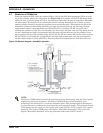
Approximately 30 seconds after the contactor pulls in, the fill valve coil should energize. There is also
a visible fill relay on the printed circuit board. It is the one located farthest from the C.T. core. The
points on this relay must be touching in order for the fill valve coil to be energized. If the points do not
touch after the built-in time delay, the sensor input may be interfering. To confirm, remove the black
and red sensor wires from terminals 6 and 10 on the PC board. Wait 30 seconds and, if the fill relay
points do not touch, replace the sensor. If they still do not touch, the basic PC board may be faulty. To
confirm, disconnect the red wire from terminal 18 and touch it to terminal 14. If the fill valve coil
activates, the basic PC board should be replaced. If it still does not activate, the fill valve coil should
be replaced. After the necessary components have been changed, water will start filling the cylinder
and begin to submerge the electrodes. Because of the high voltage across the electrodes, the water can
now conduct electricity.
Red “Change Cylinder” light on—Water at top of cylinder:
This is a common occurrence on startup. See 9.0 Startup and 12.0 Operation.
Water remains at high level and won't concentrate:
This is normal on cold startup and can be accelerated by adding a maximum of 1/2 tsp. of dissolved
salt to the cylinder on fill cycle through the plastic fill cup. See A.1.4 Low Water Conductivity.
If the unit has been operating extensively, observe for normal fill-boil-fill-boil cycle; no drainage
should occur. If drainage occurs, check for leaking drain valve or back pressure.
Unit drains continually:
May be caused by foaming and/or back pressure or by a leaking drain valve.
If cylinder is almost empty, check for magnetic pull on drain solenoid indicating miswiring. If there is
no pull, drain actuator is blocked open; remove, disassemble and clean.
If drain is occurring through activated drain valve, valve is miswired or electronics are faulty; consult
factory.
If drain is occurring through the overflow on the fill cup, this is due to abnormal restriction on the
steam line and back pressure forcing water out of the cylinder so water cannot concentrate and level
remains high. Review installation of steam line to ensure there are no blockages or excessive static
pressure in the air system.