


Special offers from our partners!

Find Replacement BBQ Parts for 20,308 Models. Repair your BBQ today.
4/12
Heatilator • Constitution EPA Fireplace • 480-1091H
Page 61
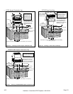
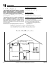
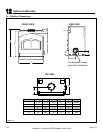
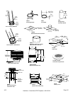
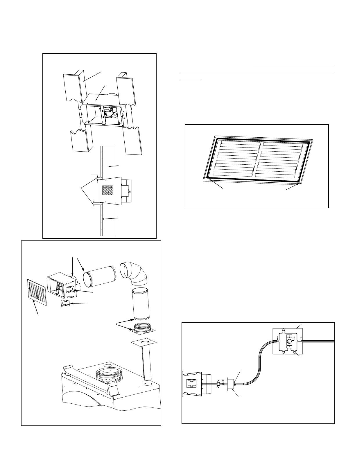
9. Seal all the way around the inside of the Return Air Grille
to prevent hot air being drawn back into the venting system
using gasketing supplied with the kit. Leave 1/4 in. (6mm)
clearance from all 4 outer edges. Trim excess gasketing.
See Figure 11.7
Securely Twist
Lock B-Vent to
Adapter
Secure B-Vent to Fan Housing
with sheet metal screws
Return Air Grille
Install with Louvers
pointed down
Bracket
Can rotate
180
o
2 x 4 Wall
Fan Housing
1/2 in. (13mm)
clearance to
combustibles
must be
maintained.
2 x 4 wall
Sheet Rock
Seal grille using gasketing supplied with the kit
Leave 1/4" (6mm) clearance from
all 4 outer edges
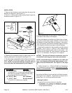
10. Install the variable speed wall rheostat (with setting on
“OFF”) in a convenient location. This switch will control the
Heat-Zone fan operation.
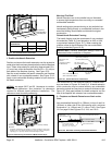
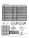
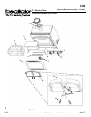
11. Remove the Junction Box. Wire 110 VAC service TO the
wall rheostat and FROM the wall rheostat to the fan Junction
Box. Use wire nuts to secure the 110 VAC service wires to
the hot (black) and neutral (white) fan wires and screw the
110 VAC ground wire to the Junction Box. See Figure 11.8.
12. Secure the Return Air Grille to the fan housing making
sure it is ush. The grille must be installed with the louvers
pointing down.
13. Complete the replace installations as per the instruc-
tions found in your Owner’s Manual.
Figure 11.5
Figure 11.6
Figure 11.7
Junction Box Removed
Wire Clamp
Wire Nuts
Junction Box
Black
White
Figure 11.8