


Special offers from our partners!

Find Replacement BBQ Parts for 20,308 Models. Repair your BBQ today.
Page 60
Heatilator • Constitution EPA Fireplace • 480-1091H
4/12
INSTALLATION
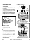
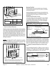
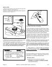
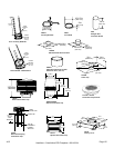
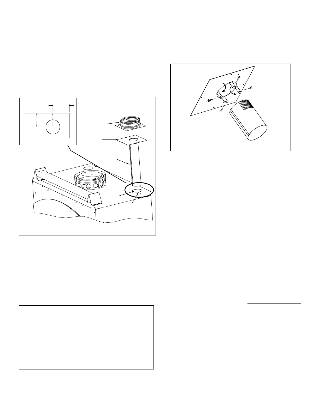
1. Remove the knockout or cover plate from the top of the
replace and discard it. See Figure 11.2.
2. Cut a 3 in. (76mm) hole in the insulation board as per the
dimensions shown in Figure 11.2
Adapter
Mounting
Plate
Starter Pipe
Knockout
Cut a 3 in. (76mm) hole
in insulation board
3-13/16 in.
(97mm)
3-1/8 in. (79mm)
C
L
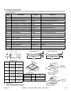
Run Length Cut Pipe
20 - 40 ft (6-12m) 2 in. (51mm)*
10 - 20 ft (3 - 6m) 8 in. (203mm)
3 - 10 ft (1 - 3m) No cut needed**
**
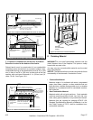
3. Determine the necessary length of starter pipe from the
following table and cut as required. See Figure 11.3.
4. The starter pipe is shipped at. After cutting to the required
length, manually roll the pipe together and snap lock into
place.
Figure 11.2
Figure 11.3
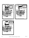
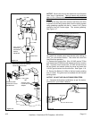
5. Slide the starter pipe into the replace, matching the holes
in the plate to the holes in the replace.
6. Place the Adapter on the Mounting Plate lining up holes.
Using the 4 sheet metal screws included in the kit, secure
the Adapter and Mounting Plate into replace. After secur-
ing to the replace, tape down the Adapter edges to the top
of the replace with aluminum tape to prevent leakage.
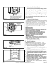
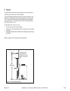
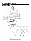
7. Determine the location for the air register and fan housing
assembly. Cut a 7-5/8 in. x 13-5/8 in. (143 x 346mm) hole
between framing members (wall studs or oor joists). The
brackets can be rotated 180° and mounted to the back side
of the 2 x 4 if necessary. See Figure 11.6 on page 61.
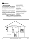
8. Attach enough 6 in. (152mm) B-Vent as required for
your installation to the fan housing. A maximum of (4) 90°
elbows is recommended. Securely twist lock the B-Vent
to the Adapter.
Also screw the B-Vent to the outlet box on the fan housing.
See Figure 11.6 on page 61.
Support duct at intervals of no
greater than 4 ft (1 m) as required by local code.
Figure 11.4
Warning Fire Risk!