


Special offers from our partners!

Find Replacement BBQ Parts for 20,308 Models. Repair your BBQ today.
4/12
Heatilator • Constitution EPA Fireplace • 480-1091H
Page 37
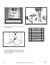
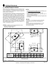
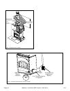
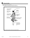
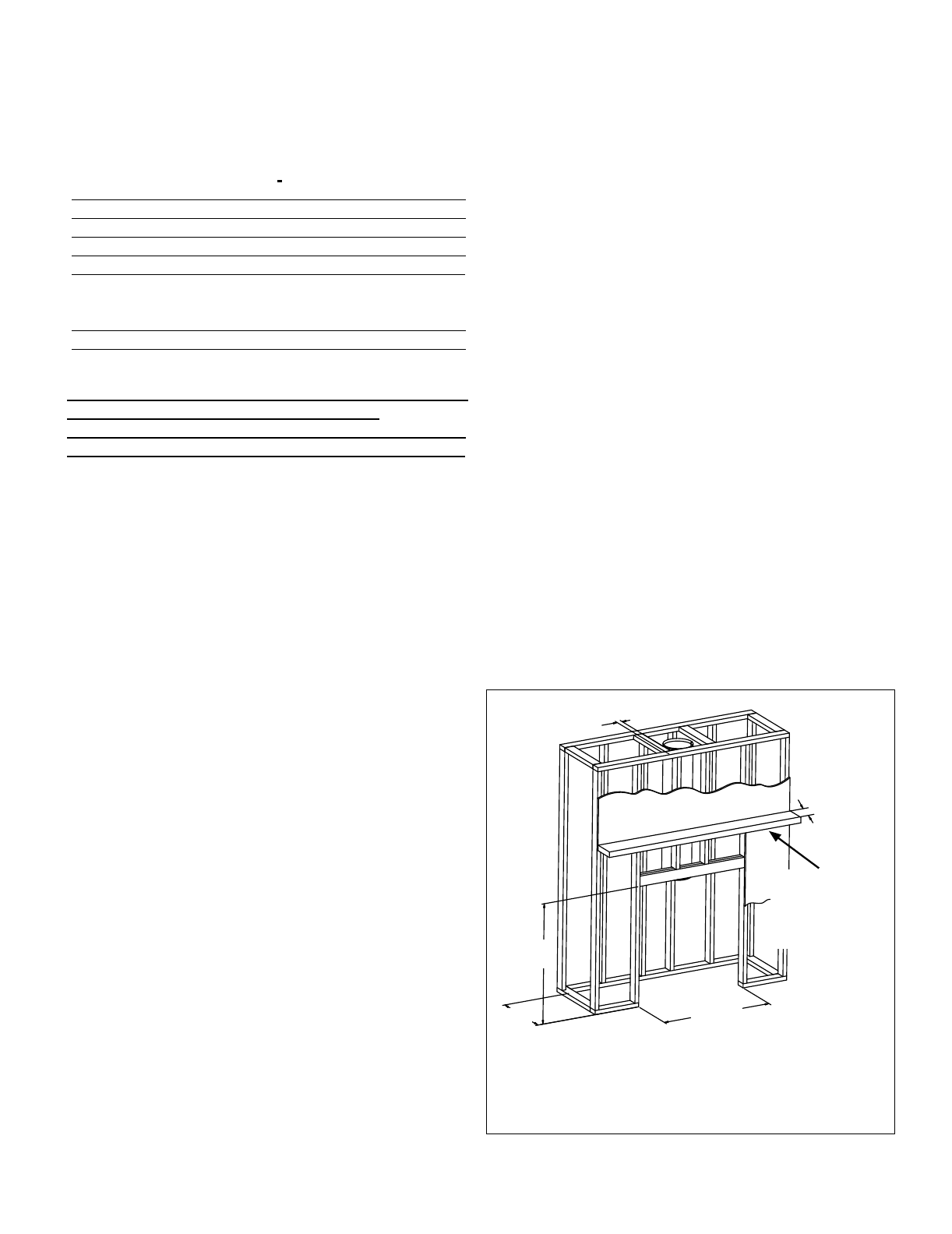
Figure 6.3 Framing the Fireplace
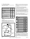
WITHIN ENCLOSURE AREA:
Appliance to backwall 1 in. (25 mm)
Appliance to sidewall 1 in. (25 mm)
Duct boots to framing 0 in. (0 mm)
Top standoffs to header 0 in. (0 mm)
Door opening to sidewall 22-7/8 in. (581 mm)
EXPOSED SURFACES
Faceplate to sidewall 16 in. (406 mm)
Heat zone air grills to ceiling 12 in. (305 mm)
MANTEL
Combustible and non-combustible mantel minimum height
from base of replace to underside of mantel
60 in. (1524 mm)
Maximum mantel depth 12 in. (305 mm)
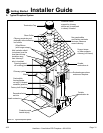
The Constitution Fireplace will t a framed opening height of
43-7/8 in. (1114 mm) tall and width of 42 in. (1067 mm). The
nished cavity depth must be no less than 24 in. (610 mm).
Framing must extend straight up all the way to the ceiling.
Figure 6.3 shows a typical framing (using 2 x 4 lumber) of
the replace, assuming combustible materials are used. All
required clearances to combustibles around the replace
must be adhered to. See Figure 6.2 on page 36. Any fram-
ing across the top of the replace must be above the level of
the top standoffs. (No recess above standoffs.)
Non-combustible mantel material minimum height from
base of replace to underside of mantel 46 in. (1168mm)
when the following enclosure construction materials are
used:
Non-combustible framing materials must be used
above replace to height of 84 in. (2134mm) from
base of replace for all construction materials, fram-
ing members, sheeting, and all nish materials.
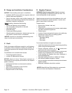
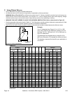
1. MINIMUM CLEARANCES TO COMBUSTIBLES
Materials which will not ignite and burn. Such materials
are those consisting entirely of steel, iron, brick, tile, con-
crete, slate, glass or plasters, or any combination thereof.
Materials that are reported as passing ASTM E 136, Stan-
dard Test Method for Behavior of Materials, in a Vertical
Tube Furnace at 750°C, shall be considered non-combus-
tible materials.
Materials made of (or surfaced with) wood, compressed
paper, plant bers, plastics, or other materials that can ig-
nite and burn, whether ame proofed or not, or whether
plastered or un-plastered shall be considered combustible
materials.
3. NON-COMBUSTIBLE MATERIALS
4. COMBUSTIBLE MATERIALS
12 in.
(305mm)
42 in.
(1067mm)
43-7/8 in.
(1114mm)
24 in.
(610mm)
2 in.
(51mm)
Position combus-
tible / non-combus-
tible mantel 60 in.
(1524mm) from
base of the replace
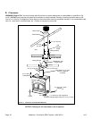
Chimney sections at any level require a 2 in. (51 mm) minimum
air space clearance between the framing and chimney section.
2. REDUCED MANTEL HEIGHT / OPTIONAL FRAMING
CONSTRUCTION REQUIRED:
5. CHIMNEY SECTIONS
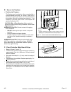
C. Frame the Fireplace