


Special offers from our partners!

Find Replacement BBQ Parts for 20,308 Models. Repair your BBQ today.
4/12
Heatilator • Constitution EPA Fireplace • 480-1091H
Page 39
7
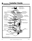
Installation of Fireplace
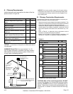
This replace will operate correctly only if adequate ven-
tilation is provided to allow proper draft to the replace
system. See Section 6.
An outside air kit must be used for combustion to mini-
mize the effects of negative pressure within the structure.
We recommend you utilize the shortest duct run to opti-
mize the performance of the outside air kit. The outside
air kit inlet should be positioned in a manner that will not
allow snow, leaves, etc. to block the inlet. In some instal-
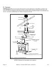
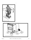
lations the air duct may need to be run vertically. In such
an installation, a 3 ft (914 mm) height difference must be
maintained from the top of the uppermost chimney sec-
tion to the outside combustion air inlet. See Figure 7.2
on page 40.
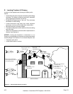
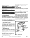
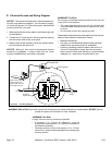
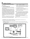
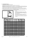
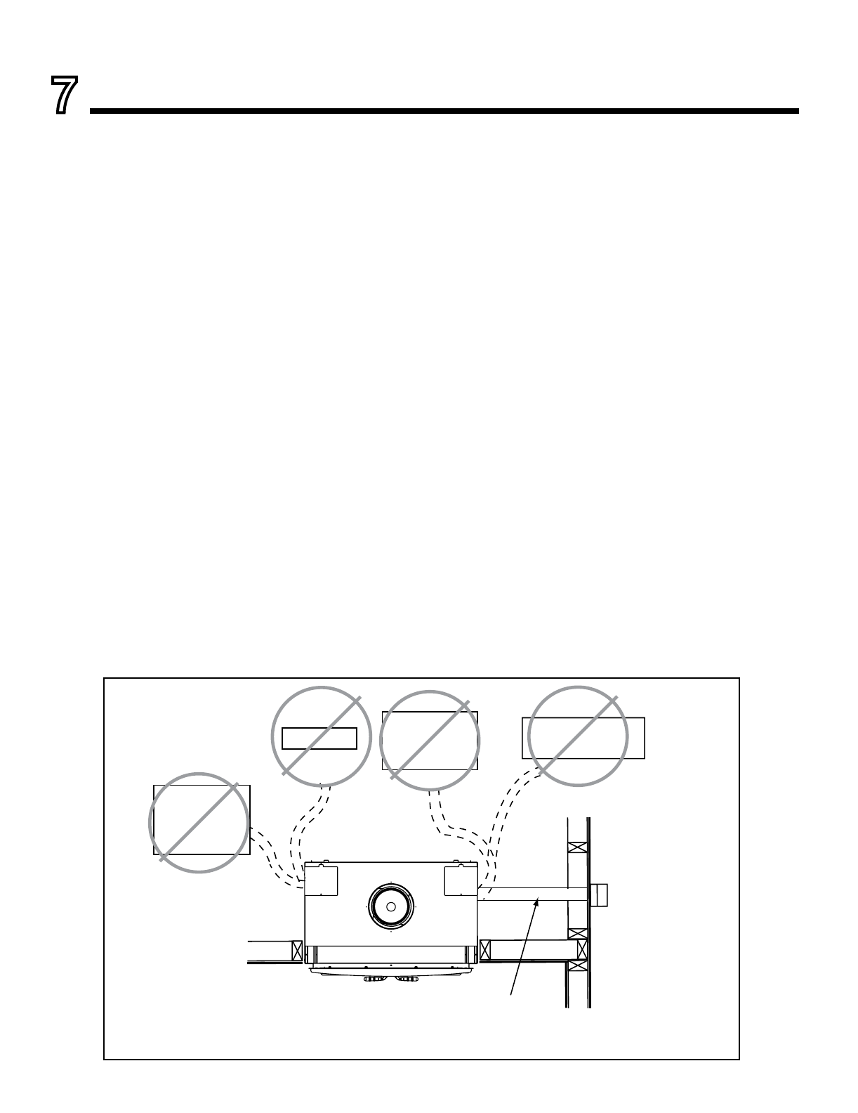
See Figure 7.1 for proper placement of outside air inlet.
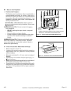
The outside air kit is installed on the right hand side of the
replace. See Figure 7.3 for handle location/operation.
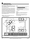
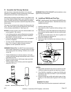
1.
Cut a 6 in. (152 mm) hole in outside wall to accommodate
air piping. See Figure 7.3 on page 40.
2. Use 6 in. (152 mm) metal flex or rigid piping
to directly connect outside air to replace
intake. Insulate the pipe to prevent frost condensation.
3. Use the supplied termination cap.
4. Seal between the wall and the pipe with silicone to
prevent moisture penetration and air leaks.
5. Seal between the termination cap and the house with
silicone to prevent air inltration.
NOTE: A control knob allows you control of the outside air
inlet. Use of outside air for combustion is required to
conserve heated air within the structure and to provide
make up air to keep the replace venting properly.
A. Install the Outside Air Kit
Outlet blocked by
snow, leaves, etc.
NO
Garage or
combustible
liquids storage
NO
Attic space
NO
Outlet placed
higher than 3 ft
below the
termination cap
NO
Use only duct materials
specified by manufacturer
Figure 7.1 Outside Combustion Air Placement