


Special offers from our partners!

Find Replacement BBQ Parts for 20,308 Models. Repair your BBQ today.
Page 56
Heatilator • Constitution EPA Fireplace • 480-1091H
4/12
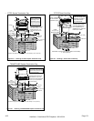
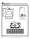
2. Fireplace and Hearth Extension are ush on the
oor:
Non-combustible ooring 20 in. (508mm) in front of and 8 in.
(203mm) to either side of the fuel opening with a minimum
thickness of 1 in. (25mm) and (“k” value = 0.49). See Figure
10.5 on page 54 and Figures 10.8, 10.9, and 10.10.
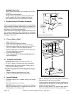
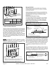
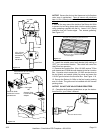
Figure 10.8 Side View of Factory Built Hearth Extension
The construction of, and materials used for a hearth exten-
sion are shown in Figures 10.5 and 10.8.
A hearth extension
of this construction may be covered with any non-combustible
decorative material and may have a maximum thickness as per
Figure 10.7 Seal gaps between the hearth extension and the
front of the replace with a bead of non-combustible sealant.
2 in. (51 mm)
required
High temperature
(300°F min.) continuous,
non-combustible sealant
Tile, stone or other
non-combustible material
Floor constructed of wood or
other combustible material
2 thickness of HX4
Hearth Ext
or equivalent insulation
(see Table below)
Fireplace
Protective
Metal Hearth
Strip
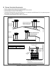
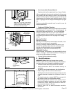
Figure 10.7 Hearth Extension Construction
NONCOMBUSTIBLE
DECORATIVE MATERIAL
(2) HX4 MICORE FACTORY
BUILT HEARTH EXTENSION
(Each HX4 = 1/2 in. (13mm) thick)
HEARTH METAL STRIPS
GAP (SEAL WITH NONCOMBUSTIBLE SEALANT)
UP TO BOTTOM OF FASCIA
6 in. (152mm)
1/2 in. (13mm)
IMPORTANT! Hearth extension design must be
determined before installation of replace.
Raised Hearth Extension Framing
The hearth framing must be constructed of non-combusti-
ble materials (Table 10.2) and placed on an HX3 or HX4,
or equivalent material (Figure 10.7). When creating the
platform, allow for the thickness of the non-combustible
nishing materials (Figure 10.10).
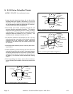
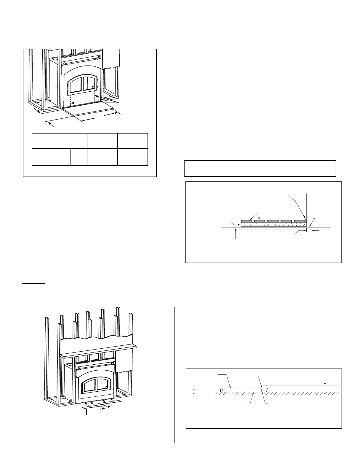
B
8 in. (203mm)
from each side of
fuel loading door
A
Model #
Constitution
A B
41 20
1041 508
Figure 10.5 Hearth Extension Dimension
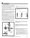
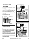
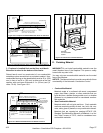
Position and secure the hearth extension over the protective
metal strips that have been placed partially under the replace
front. These strips should be protruding approximately 2 in.
(51 mm) from under the replace front and 2 in. (51 mm) on
both sides of the replace opening. See Figure 10.6.
Seal the crack between the hearth extension and replace
with a bead of non-combustible sealant. See Figure 10.12.
Apply a non-combustible nishing material of your choice to
the hearth extension.
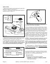
1. Position the Hearth Extension
Protective metal strips are placed 2 in.(51mm) under the front of the
fireplace and must extend beyond the front and sides of fireplace
opening by 2 in. (51mm). Nail or screw metal strips in place.
Pallet
Mounting
Brackets
1 in. (25mm) Overlap
Figure 10.6 Positioning the Protective Metal Hearth Strips