


Special offers from our partners!

Find Replacement BBQ Parts for 20,308 Models. Repair your BBQ today.

CE4000 Cable Explorer TDR
User Manual
8
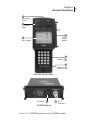
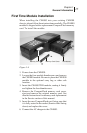
CM1000 MAINFRAME AND CE4000 MODULE
1. Mainframe Input/Output
The mainframe I/O section, located at the top of the unit,
provides a female RS-232 9-pin connector (DB-9) for a serial
computer interface. In addition, there is an external power
connection to accept power from the DC power adapter
provided with the unit.
2. Plug-In Module Slot
The plug-in module slot accepts the CE4000 TDR or the
CM1000 Cable Modem Network Analyzer module.
Warning! Do not remove or install a module with the base unit
powered on or connected to the system or other
equipment. Always turn unit off before removing or
installing a module.
3. CompactFlash memory slot
This slot located on the lower right hand side of the unit
houses the mainframe’s CompactFlash memory card. This
memory card further enhances the unit’s ability to
accommodate future memory expansion/upgrades.
4. Battery Access
An access panel at the lower back of the unit provides easy
access to the user-replaceable battery pack.
5. Full Color Display
The full color display provides clear, easily discernable test
and menu screens in both dark and full sunlight conditions.
6. Status LED indicators
Seven LED indicators show the status of downstream
connection, upstream connection, link, Ethernet connection,
power and battery functions.
7. RF “F” Connector
Connection to the cable under test. Field replaceable.
8. Fan Outlet
Exhaust from cooling fan—Do not block airflow.