


Special offers from our partners!

Find Replacement BBQ Parts for 20,308 Models. Repair your BBQ today.

Chapter 3
Measurements
51
views of the data are available by pressing the Nest (F1) function
key to display the next fault or the Adjust (F2) function key to
adjust the vertical gain or horizontal gain (range).
Two stored files may be compared by pressing the Compare (F3)
function key and selecting a second saved file.
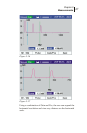
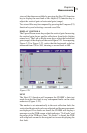
DISPLAY CONTROLS
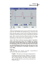
The Up and Down arrow keys adjust the vertical gain. Increasing
the vertical gain shows smaller reflections from faults (higher
return loss). The Left or Right arrow keys adjust the horizontal
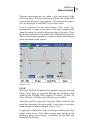
gain (range) of the display as shown in Figure 3-21. In comparing
Figure 3-21 to Figure 3-22, notice that the horizontal scale has
increased from 250 to 500, showing a second fault at 480.
Figure 3-21
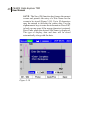
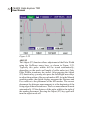
NEXT
The Next (F1) function will sequence the CE4000’s Auto test
mode from the first fault to any subsequent faults on the cable
under test (Figure 3-22).
The marker is set automatically to the next reflection fault, the
vertical and horizontal scales are adjusted and the measurements
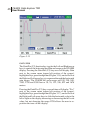
are displayed. If no faults are found, the CE4000 will display a
message over the TDR screen, which indicates: “No Faults“ and
the range of the TDR test. Once “No Faults” is found, the TDR
will wrap back around to the original test screen displaying the
first fault.