


Special offers from our partners!

Find Replacement BBQ Parts for 20,308 Models. Repair your BBQ today.

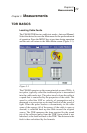
CE4000 Cable Explorer TDR
User Manual
32
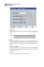
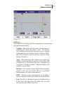
energy and a lower frequency and thus more energy is transmitted
and less loss is present in the cable. This allows a longer range.
The range is dependent on the VOP and pulse width used for the
test. A table providing maximum ranges for each pulse width is
provided in the Appendix.
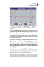
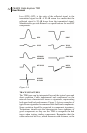
Figure 3-3
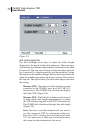
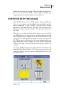
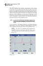
THE TDR TRACE
The TDR trace provides detailed information about the cable
under test. The horizontal axis is calibrated in distance, either
feet or meters. The vertical scale is calibrated in dB of loss with
both positive and negative axes. The positive axis represents
reflections, which result from impedances higher than the nominal
75W impedance of the cable. The negative axis represents
reflections that result from impedances lower than the nominal
75W impedance of the cable. Thus, an open cable will result in
a positive reflection pulse and a shorted cable will result in a
negative inclined reflection pulse. A perfect cable, terminated in
its characteristic impedance will absorb all of the energy from
the incidence pulse and no reflection will be seen on the TDR.
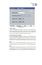
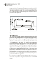
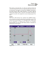
High impedance series mismatches (corroded or loose connectors,
loose seizure screws, and radial cracked sheath) will produce
positive inclined trace signatures.
Low impedance parallel mismatches (kinked cable, water ingress,
and shorts) will produce a negative inclined trace on the TDR
screen.