


Special offers from our partners!

Find Replacement BBQ Parts for 20,308 Models. Repair your BBQ today.

Chapter 3
Measurements
31
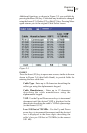
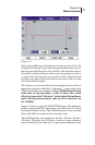
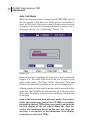
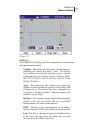
Figure 3-2
Short pulse widths are advantageous for two reasons. First, the
time period of the pulse prevents seeing reflections that occur in
the time period between the rise and fall of the incidence pulse.
Secondly, multiple reflections that are close together are seen as
a single fault because the time period of the reflected pulse
obscures any other reflections between the time of the rise and
fall of the reflected pulse.
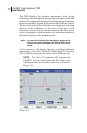
The distance associated with the time during the rise and fall of
the incidence pulse is called the “dead zone”—an area where the
TDR cannot make measurements. The CE4000 eliminates this
dead zone by incorporating a built in delay line, which
effectively moves the “0 distance” to the right of the incidence
pulse allowing measurements right up to the connector on
the CE4000.
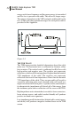
Figure 3-2 shows a typical CE4000 TDR display. The incidence
pulse is shown to the left of the display (just left of the “0” on the
horizontal distance scale). The reflection pulse can be seen just
below the 200-foot mark on the horizontal scale.
The CE4000 offers pulse widths of 10 nSec, 20 nSec, 50 nSec,
100 nSec, 200 nSec, and 350 nSec. Faults at longer distances
may be masked by the cable loss. Longer pulses represent more