


Special offers from our partners!

Find Replacement BBQ Parts for 20,308 Models. Repair your BBQ today.
CE4000 Cable Explorer TDR
User Manual
38
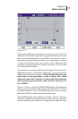
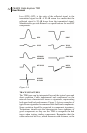
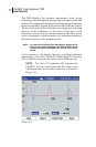
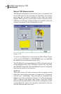
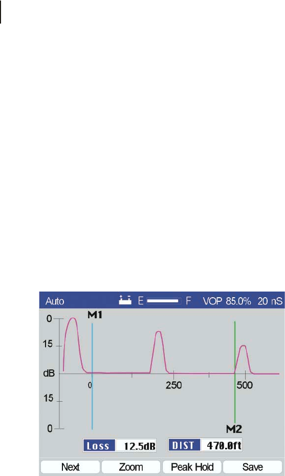
The TDR displays the distance measurement both on the
horizontal scale and digitally based on the placement of the M2
marker. M1 is automatically placed at the beginning of the cable
under test and M2 is placed at the point of the reflection (fault).
The loss at the point of the reflection is also displayed, indicating
the loss to the reflection—or the ratio of the level of the
reflection to the level of the incidence pulse in dB. The vertical
scale is logarithmic, with level marks, also indicating the ratio of
the reflected pulse to the incidence pulse.
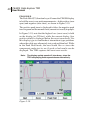
Note: An open or shorted cable would only measure the
loss of the cable between the TDR and the fault,
since both (short and open) will reflect 100% of the
pulse.
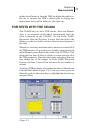
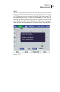
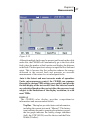
At the bottom of the display the user is offered additional
function keys, Next (F1), Zoom (F2), Peak Hold (F3) and Save
(F4) to further investigate the results of the TDR auto test.
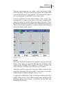
NEXT - The Next (F1) function will sequence the
CE4000’s Auto test mode from the first fault to any
subsequent faults on the cable under test, as shown in
Figure 3-8.
Figure 3-8