


Special offers from our partners!

Find Replacement BBQ Parts for 20,308 Models. Repair your BBQ today.

Chapter 3
Measurements
45
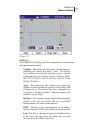
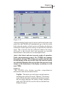
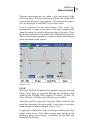
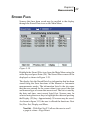
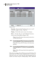
Distance measurements are made at the beginning of the
reflection pulse. Position the marker at the point on the TDR
trace where the pulse rises quickly. The measured distance
will be displayed in the DIST box on the screen.
Loss is measured in the same fashion. The actual loss
measurement is made at the peak of the pulse automatically
when the marker is placed on the rising edge of the pulse. Thus,
the distance and the loss are made from a single marker position.
The loss measurement window is roughly as wide as the reflected
pulse displayed on the screen.
Figure 3-14
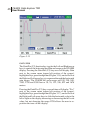
PULSE
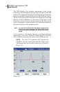
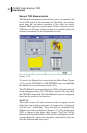
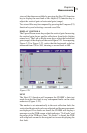
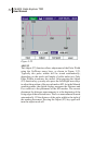
The Pulse Width (F2) function key permits using the Left and
Right Arrow keys to sequence through the available pulse
widths of the CE4000. Pulse widths of 10 nSec, 20 nSec, 50
nSec, 100 nSec, 200 nSec and 350 nSec are available.
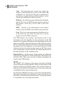
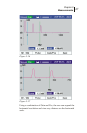
The right arrow key increases the pulse width, while the left
arrow key decreases the pulse width. A new trace is provided
when the pulse width is changed (Figure 3-15).
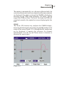
Longer pulse widths allow you to test longer cables and to view
higher return losses. Since they provide more energy in the
incidence pulse, more energy is reflected by the fault and
detectable for display.