


Special offers from our partners!

Find Replacement BBQ Parts for 20,308 Models. Repair your BBQ today.

4-03 9 480-1081
North Star
EPA Certied Fireplace
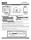
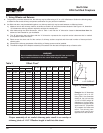
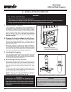
88-7/8"
44-7/16"
23-5/8"
62-13/16"
42"
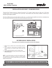
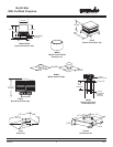
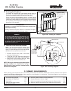
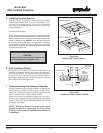
Figure 9B
Installation Along a Wall or an Exterior Chase
Figure 9C
Corner Installation
WARNING! Do not draw outside air from garage spaces. Exhaust products of gasoline engines are hazardous.
Do not install outside air ducts such that the air may be drawn from attic spaces, basements or above the roong where
other heating appliances or fans and chimneys exhaust or utilize air. These precautions will reduce the possibility of
replace smoking or air ow reversal. The outside air inlet must remain clear of leaves, debris ice and/or snow. It must be
unrestricted while unit is in use to prevent room air starvation which can cause smoke spillage and an inability to maintain
a re. Smoke spillage can also set off smoke alarms.
WARNING! To prevent contact with sagging or loose insulation, the replace must not be installed against vapor barriers
or exposed insulation. Localized overheating could occur and a re could result.
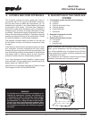
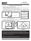
Figure 9A - Fireplace Locations
1. Fireplace Locations and Space Requirements
Several options are available to you when choosing a location for your replace. This replace may be used as a room divider,
installed along a wall, across a corner or used in an exterior chase. See Figure 9A.
Locating the replace in a basement, near frequently opened doors, central heat outlets or returns, or other locations of considerable
air movement can affect the performance and cause intermittent smoke spillage from the front of the replace when no outside
air is used. Outside air is required for combustion. (see page 21). The North Star Fireplace comes equipped with an outside
air inlet to feed combustion air from outside the home, along with an outside air termination cap. Consideration should be given
to these factors before deciding on a location.
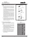
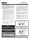
CLEARANCES!
A minimum 1” air clearance must
be maintained at the back and
sides of the replace assembly.
Chimney sections at any level
require a 2” minimum air space
clearance between the framing
and chimney section.
51"
23-1/2"
10"
E. PRE-INSTALLATION PREPARATION
As a room
divider
A
long a wall
In an exterior chase or
projecting into a garage
Across a corner
These are
rough
framing
dimensions
only.
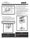
Figures 9B and 9C show two typical installations for the outside air kit. Allowances must be made for 90° bends. Less
space is required when ducting goes directly outside without forming elbows.