


Special offers from our partners!

Find Replacement BBQ Parts for 20,308 Models. Repair your BBQ today.

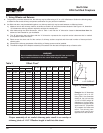
4-03 15 480-1081
North Star
EPA Certied Fireplace
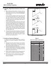
1. An outside air inlet must be provided for combustion and must
remain clear of leaves, debris, ice and/or snow. It must be
unrestricted while unit is in use to prevent room air starvation
which can cause smoke spillage and an inability to maintain a
re. Smoke spillage can also set off smoke alarms.
2. The replace is to be secured to the mobile home structure.
Use same holes that attached the replace to the pallet to
secure it to the oor use 1/4” x 2” lag bolts or equivalent.
3. Unit must be grounded with #8 solid copper grounding wire or
equivalent and terminated at each end with N.E.C. approved
grounding device.
4.
Refer to Minimum Clearances to Combustibles on page 5 and
chimney components on pages 6-8.
5. Floor protections requirements on page 17 must be followed
precisely.
6. Use silicone to create an effective vapor barrier at the location
where the chimney or other component penetrates to the
exterior of the structure.
7.
Follow the chimney and chimney connector manufacturer’s
instructions when installing the ue system for use in a mobile
home.
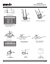
NOTE: Top sections of chimney must be removable to allow
maximum clearance of 13.5’ (411cm) from ground level for
transportation purposes.
8. Burn wood only. Other types of fuels may generate poisonous
gases (e.g., carbon monoxide).
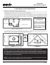
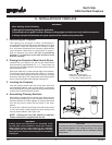
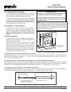
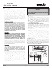
8. Mobile home installation
You must use the outside air termnination cap supplied
with your North Star Fireplace for installation in a
mobile home. If you use an alternative material it must
be designed to prevent material from dropping into the
area beneath the mobile home, and to prevent rodents
from enterting from the outside.
CAUTION:
The structural integrity of the mobile home oor, wall and
ceiling/roof must be maintaned. (i.e., Do not cut through
oor joist, wall stud, ceiling truss, etc.)
WARNING!
NEVER DRAW COMBUSTION AIR FROM A WALL,
FLOOR OR CEILING CAVITY OR FROM ANY
ENCLOSED SPACE SUCH AS AN ATTIC OR GARAGE.
WARNING!
DO NOT INSTALL IN SLEEPING ROOM.
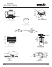
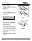
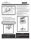
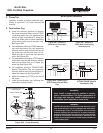
9. SL-300 Series MH842 Celing/Roof Thimble
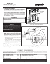
1. Locate the point where the chimney will exit the roof by
plumbing down to the center of the chimney. Lay out, cut and
frame a 14-1/2” square opening (measured on the horizontal)
through the ceiling and roof structure. See Chapter 25 of the
Uniform Building Code for Framing Details.
2. The thimble must extend completely through the roof structure
shielding combustible materials. Five location holes have been
provided to allow for a variety of ceiling/roof thicknesses. The
MH841 Thimble Extension is required when the ceiling/roof
thickness exceeds 12-1/2”. The extension should overlap
the thimble one inch.
3. To attach the extension to the thimble, drill 1/8” holes through
the outer shield of the thimble using the predrilled holes in the
extension as guides. Attach the extension to the thimble using
the screws provided with the extension.
4. Install the thimble assembly and nail it securely to the framing
members.
5. Center the ashing over the chimney and nail it to the roof
using the Stormguard nails provided. Keep gaps between the
ashing plate and the roof to a minimum.
6. Caulk the flashing plate and roof junction as well as the
vertical seam on the ashing. All nail heads must be caulked
with a roong sealant.
7. Finish assembling the chimney storm collar and termination
cap following the installation instructions provided with
them.
CHIMNEY
FLASHING
PLATE
JOISTS
NAIL
THIMBLE
FLASHING
FLASHING
CHIMNEY
FLASHING
PLATE
NAIL
THIMBLE
SCREW
THIMBLE
EXTENSION
Figure 15A - Installing an MH842, Conguration 1
Figure 15A - Installing an MH842, Conguration 2