


Special offers from our partners!

Find Replacement BBQ Parts for 20,308 Models. Repair your BBQ today.

480-1081 10 4-03
North Star
EPA Certied Fireplace
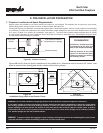
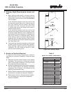
43-7/8"
42"
2"
24"
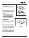
Position mantel
60” from base of
the replace
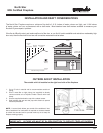
WARNING!
Do not apply combustible nishing materials over
any part of the front of this replace or a structure
re may result. The metal replace face may only
be covered with noncombustible materials such
as ceramic tile, brick, or stone. Do not cover or
block any cooling air slots.
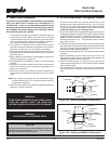
CLEARANCES!
A minimum 1” air clearance must be maintained at the back and sides
of the replace assembly.
Chimney sections at any level require a 2” minimum air space
clearance between the framing and chimney section.
Figure 10A- Framing the Fireplace
The North Star Fireplace will t the framed opening width of
43-7/8” tall. The nished cavity depth must be no less than 24”.
Framing must extend straight up all the way to the ceiling.
Figure 10A shows a typical framing (using 2 x 4 lumber) of the
replace, assuming combustible materials are used. All required
clearances to combustibles around the replace must be adhered
to. Any framing across the top of the replace must be above
the level of the top standoffs.
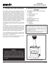
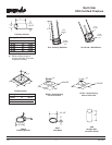
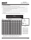
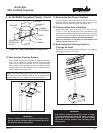
F. CHIMNEY REQUIREMENTS
When planning your fireplace location, the chimney construction and necessary clearances must be considered. The fireplace
system and chimney components have been tested to provide exibility in construction. The following gures are the minimum
distances from the base of the replace.
2. Framing the Fireplace
1. Min overall straight height 13 ft.
2. Min height with offset/return 14.5 ft.
3. Max height 50 ft.
4. Max chimney length between
an offset and return
12 ft.
5. Maximum distance between chimney stabilizers 35 ft.
6. Double offset/return minimum height 20 ft.
7.
Maximum unsupported chimney length between the offset and return
6 ft.
8.
Maximum straight unsupported chimney height above the replace
35 ft.
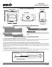
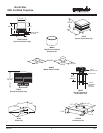
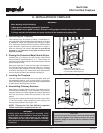
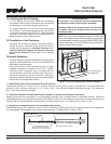
3. Electrical Access and Wiring Diagram
14-2 w/ground
Standard wall mount with
Junction Box
14-3 w/ground
WIRE NUT
WHITE
GREEN
BLACK
BLACK
RED
WHITE
Match colors to wire
harness (red to red,
white to white, etc) and
secure with a wire nut
NOTE: The manual override switch, rheostat speed
control and cover plate are supplied. You will need to
supply: 14-3 wire with ground; 14-2 wire with ground;
standard wall mount junction box; wire nuts.
1. Remove outside air cover plate on the bottom
right side of the replace.
2. Thread the 14-3 with ground wire through the
opening with the strain relief on the cover plate.
3. Match colors to wire harness, (red to red, white
to white, etc) and secure with wire nuts.
Figure 10B- Fan Wiring Diagram
NOTE: Wiring for blowers must be done before
framed enclosure is completed. If using a
Heat Zone kit, it also must be installed before
enclosure is complete.